

About The Product
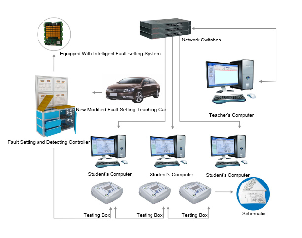
The vehicle teaching and evaluation platform is based on the whole vehicle. Without destroying the original vehicle circuit, connect to the fault setting terminal through the original wiring harness. The fault setting terminal connect to the test bench through a special wire harness. Then through wireless WIFI networking, form the multi-functional teaching equipment for circuit teaching and training assessment of various systems of the whole vehicle. The equipment is equipped with a mechanical fault setting terminal, which can set fault like open circuit, short circuit, accidental, poor contact, and CAN line reverse connection. By replacing the equipped harness and the detection panel, the fault setting, detection and elimination functions of different parts and different modules of the whole vehicle can be realized, so as to meet the requirements of automobile teaching, training and practical operation.
Features
1. Fault setting controller: with 20 fault setting terminals and 20 fault detecting terminals
-
Without changing the original car harness, use the fault setting terminal, you can set up more than 20 units of fault setting controllers for student detection terminal through the wireless WIFI network, which can do diagnosis, measurement and fault setting of the original car electronic control system.
-
Mechanical fault setting terminal realizes the fault setting of open circuit, virtual line connection, short circuit to ground, and short circuit to positive pole by changing plug-ins and short circuit jumper for different functions on the panel. Changing the different wiring harnesses and detection panels while the mechanical fault setting terminal is unchanged can realize the training operation of different systems.
-
Each training system can read the fault code and waveform through the decoder and oscilloscope.
-
Each training system can do troubleshooting analysis through voltage measurement comparison by multimeter.
2. Students detection terminal Size: 300×223×90mm (L* W*H)
-
The detection terminal panel adopts the PCB board, which is provided with detection terminals for testing and training of different electronic control systems;
-
Each detection terminal is equipped with a corresponding color-coated circuit diagram for students to detect different electronic control systems. Students can understand and analyze the composition and working principle of each control system of the vehicle through the combination of hardware and software.
-
Contains more than 20 training module systems. The detection circuit diagram is the same as the original car circuit diagram. The module system is slightly different depending on different car model.
-
Teacher software B-D01002
The system is divided into resource management module, course center module, test assessment module, face-lift plate module, system management module, course production module and so on.
u The main control server is installed with the face-change network version of the multimedia theory-practice integration training appraisal system main program and networked with all the student machine, forming a local area network.First look up the status of the local connection of each computer, and look up the IP address of each computer in the network.
u Search for the server on local area network. If no server is found, the system will display “The device is not connected to the system” and will search once every 1 minute until a server is running.
u The wireless network intelligent fault setting driver module's face-changing network version of the multimedia theory-practice integration training system has two modes: "free practice" and "training assessment".
4.Student software
u Obtain the module information from a network server (the module name, all the available failure names, number of chosen failures), and show the circuit diagram identical with the module. When a teacher replaces a module, the server will instruct the teacher to change the diagram into the one identical with that of the module.
u The student are allowed to test, measure, locate and find failures on the face-lift plate, and answer the questions in accordance with the tips and circuit diagrams on the interface (the teacher can see the answer result).
u Student can log in for exam assessment (the teacher's automatic statistical score shows the results of all students)
-
The software uses the menu mode, which can detect whether a related signal line for direct measurement is switched to the corresponding system when choosing a system.
u Student are allowed to find the system circuit diagram, maintenance manual, system principle, waveform and technical data of the corresponding model on the computer.
5. Detection module assembly B-D01003
u The detection module assembly is installed with PCB detection board on the surface, which is made of high-quality glass fiber PCB board, each system control unit, actuator, sensor connector pin diagram are painted on the board.
u The whole vehicle is connected by a special wire harness, and the voltage, resistance and waveform signals of the corresponding system circuit of the real vehicle can be detected.
u Including 6 system detection modules: engine electronic control system detection module, ABS electronic control system detection module, automatic transmission system detection module, automatic air conditioning control system detection module, comfort system detection module, lighting control system detection module.
-
Special wire harness
u Special universal detection harness, including A\B\C\D, 4 sets of butt plugs can detect each electronic control system module of the vehicle;
u 6 special electronic control module detection harness: engine electronic control system module detection harness, ABS electronic control system module detection harness, automatic transmission system module detection harness, automatic air conditioning control system module detection harness, comfort system module detection harness, lighting control system module detecting the wiring harness, including complete plug and socket;
Engine sensor, actuator universal inspection harness, including complete (1-6) pin butt detection connector.