


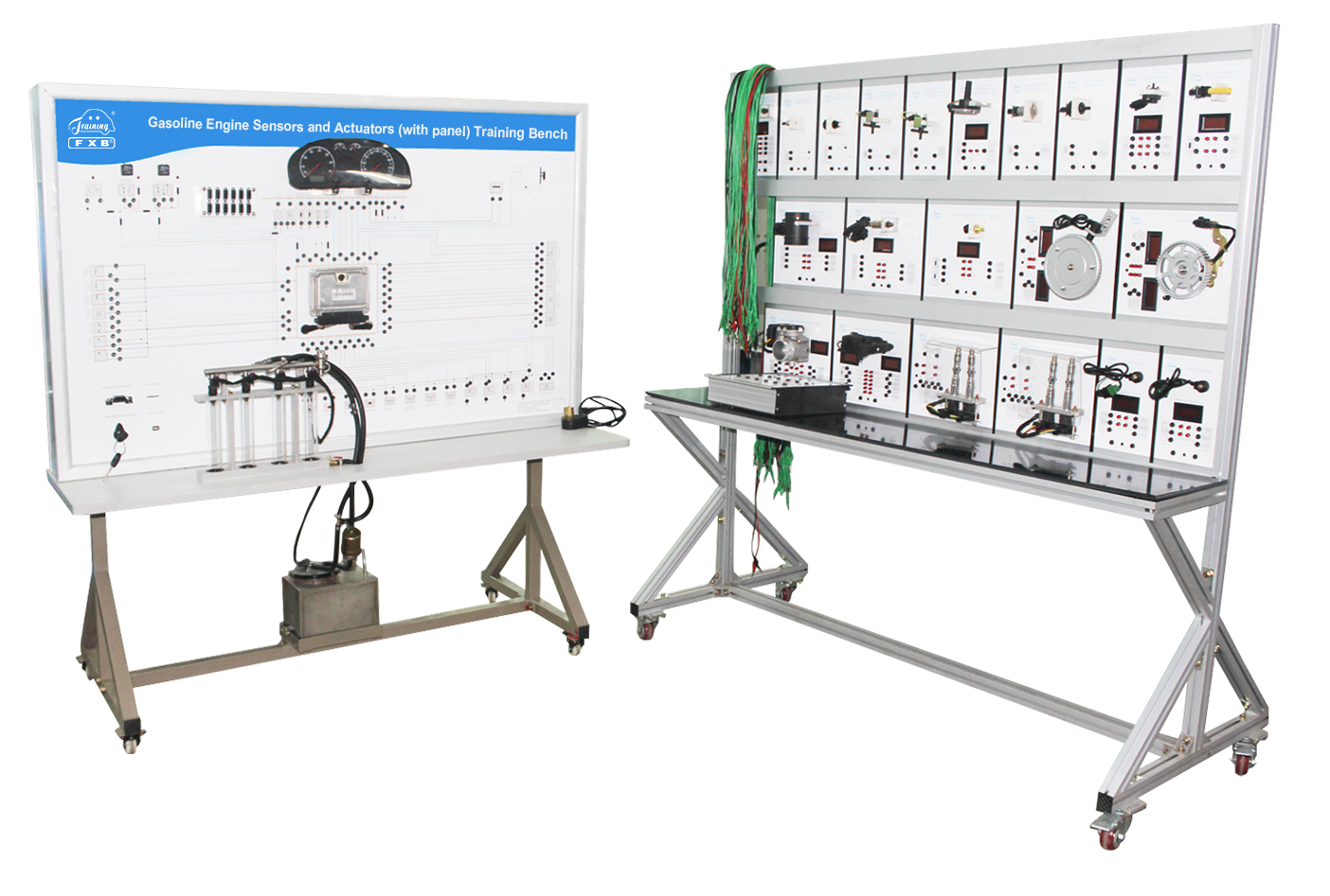
1. The training equipment is designed based on the original complete engine sensors and actuators. It adopts the crankshaft signal wheel to simulate engine operation, such as ECU controls, fuel pump works, fuel injectors work, spark plug ignition, etc. So it can demonstrate the working process of engine sensors and actuators.
2. It includes one training panel and one training bench. The sensors and actuators on the training bench can be connected to the corresponding terminals on the training panel by connection wires, then the sensors and actuators works normal.
3. The training panel equipped with ECU, Diagnostic socket, Dashboard, Ignition switch, Ignition system, Fuel tank, Detection terminal, Wireless fault-setting and appraisal system by Tablet.
4. The training bench equipped with Accelerator pedal position sensor, Electronic throttle, Air-fuel ratio oxygen sensor, Hall sensor, Coolant temperature sensor, Air flow meter, Independent ignition coil and ignition module, Canister solenoid valve, Oxygen sensor, Intake air temperature sensor, Knock sensor, Crankshaft position sensor, Oil surface temperature sensor, Turbocharging air recycle solenoid valve, Turbocharging pressure sensor, Turbocharging pressure limit solenoid valve, Camshaft regulating valve, Oil pressure switch, Coolant level switch.
5. The training panel has painted color circuit diagram, so students can compare the diagram and the actual components to learn and analyze the working principles of the engine sensors and actuators.
6. It’s installed with detection terminals to directly detect voltage, current, resistance, waveform.
7. The training panel is installed with diagnostic socket for connecting vehicle scanner. Then reads fault codes, clears fault codes, and reads data stream from the ECU.
8. The frequency meter or voltmeter can intuitively show the changes of sensor parameters.
9. Control the ignition and injection timing of the engine through the crankshaft signal and camshaft signal generated to visualize the ignition and injection sequence.
10. Variables of engine pedals, ignition frequency, fuel injection frequency, and throttle opening by changing the accelerator pedal position.
11. Ignition injection frequency, crank signal frequency, camshaft signal frequency, throttle position sensor signal, accelerator pedal position sensor and other signals can be detected by the instrument.
12. Internal control program of the ECU to reflect multi-point port injection.
13. It demonstrates the design of the electronic circuit by understanding the internal circuit diagram of the engine control unit ECU
14. It converts AC 220V power into DC 12V for panel works. The DC 12V protects the equipment against short circuit.
15. Lockable casters are installed on base frame to make it stable and movable.
16. The language for this equipment can be English or customized language.
17. The equipment is provided with operation manual, it’s helpful for training and learning.
18. Equipped with wireless fault-setting and appraisal system, teachers set faults by tablet PC then ask students to detect and find the fault. It’s helpful for teachers to know about students’ learning status, also can improve students’ skills in troubleshooting.
19. Accessories: Connection wires are provided for connecting the training panel and training bench.
1. Reference dimension: 1600mm x 700mm x 1700mm (length x width x height)
1800mm x 700mm x 1800mm (length x width x height)
2.External power supply: A.C. 220V±10% 50/60Hz
3. Operating voltage: DC 12V
4. Operating temperature: -40℃ ~ +50℃