

1.The intelligent training and testing platform of the power battery management system is graphically controlled through the human-computer interaction interface, so as to improve the teaching efficiency and teaching effect of teachers, and facilitate the learning of students.
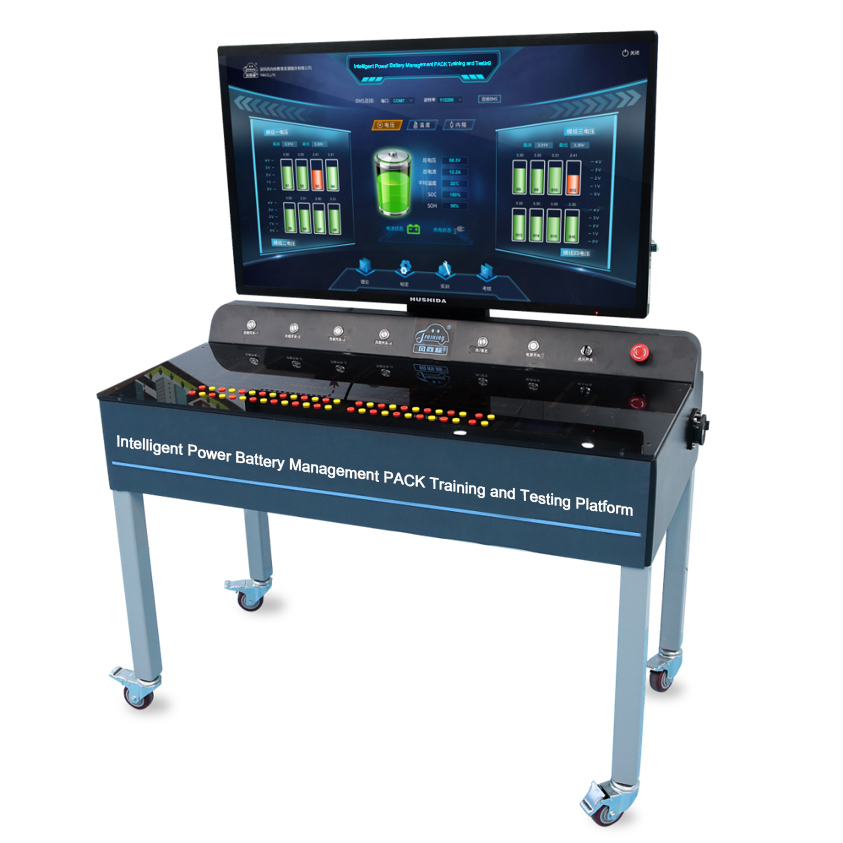
2.Intelligent power battery management PACK training and testing platform consists of lithium iron phosphate battery cell, BMS, 12V switch power supply, car charger, high voltage distribution box, pre-charge resistors, capacitors, relays (total negative relays, total positive relays, pre-charge relays, slow charge relays), PBC board, connecting copper bars, fastening bolts, current sensors, high-voltage wiring harness, low-voltage wiring harness, maintenance switch, discharge load , discharge load condition switch, 43-inch multi-media terminal, power battery PACK troubleshooting and testing intelligent teaching system,etc.
3.Meet the needs of general fault diagnosis and troubleshooting training of power battery , battery management system, on-board charging system.
Product Features
The intelligent power battery management PACK training and testing platform is divided into two major modules: the power battery PACK troubleshooting and testing console and the intelligent simulation teaching system.
1. Power battery PACK troubleshooting and testing platform
- The training platform adopts a 51V/20AH lithium iron phosphate power battery pack with a general battery management system, and visually shows the power battery connection mode and charging and discharging process.
- The battery pack of the training platform is composed of 16 3.2V/20AH single movable batteries, which are divided into two groups according to each group of eight batteries. Each group of batteries is equipped with a signal collector. The battery data collected by the signal collector passes through the CAN BUS to the BMS manager for analysis and processing, and the BMS manager reports the battery parameters and BMS management status to the host computer for display through the 485 interface.
- The training platform is equipped with essential components for mainstream electric vehicle battery management systems .such as emergency switch, high voltage interlock switch, main relay, precharge relay, precharge resistor, charging relay, and Hall current sensor, which can truly illustrate the whole process of battery management.
- The training platform is equipped with a national standard 220V AC charging interface and a high-voltage charging module. The BMS main control module can detect the insertion, dial-out and charging current condition of the charging gun, and transmit these status information to the multi-media terminal for display.
- The training platform is equipped with a 12V low-voltage electric bottle and a low-voltage charging module, which can show the charging process of the high-voltage battery to the 12V low-voltage battery.
- The intelligent platform supporting load system can be adjusted in one to four gears to flexibly control the discharge efficiency of battery pack.
- The high voltage inside the battery box is connected by copper bars, which have large overload capacity, strong connection reliability, neat and beautiful .
- The training platform BMS management system is composed of a main control module and a signal collector module, and multi-media devices can communicate with each other. The main control board controls the battery cell voltage, the total voltage of the power battery pack, temperature, internal resistance, total current, SOC, SOH, etc. The data is transmitted to the multimedia terminal ≥43 inches, and the data information is dynamically displayed through graphical software. The main control board can execute the multi-media terminal instructions to realize the opening and closing of the charging relay, the main relay, and the pre-charge relay, and start or stop the battery data collection .
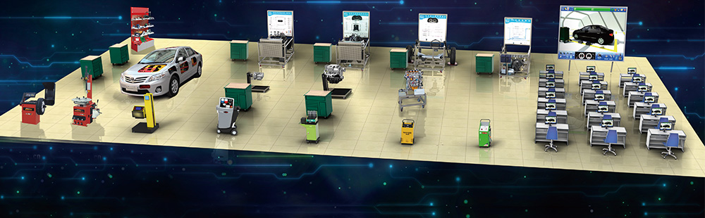
- There are two discharge modes for the platform, one is internal discharge, which is discharged through the load of the device, and the other is external discharge, which connects to the intelligent platform of pure electric vehicle drive system installation and detection technology intelligent platform.
- The stand is equipped with swivel casters with locking mechanism; the stand is made of steel, the panel is flat, and the ≥43-inch display is supported by a pole, which can be rotated around 360°, and the tilt angle can be adjusted back and forth.
2.Intelligent simulation teaching system
- System contents
- The intelligent simulation system dynamically monitors the power battery pack, and graphically controls the intelligent training platform of the power battery management system through the human-computer.
- The intelligent simulation system is installed in a 43-inch high-definition multi-media terminal for dynamic display, and the intelligent teaching system realizes information interaction with the intelligent training platform of the power battery management system through the communication protocol.
- When the system starts, it enters the self-checking state, and detects the BMS main control board, two BMS slave control boards, CAN communication, 485 communication, etc., and judges the detection result. If the result is abnormal, it can be re-detected. And If the result is normal , the detection result can be started normally. When powering on, the BMS main control board is first powered on. After a delay of 1 second, the two BMSs are powered on from the control board control circuit, and then the BMS is powered on from the acquisition circuit of the control board to start collecting voltage, temperature, discharge (or charging). ) Current. In the discharging state, when the battery status is normal, the pre-charge relay is turned on first, the main relay is turned on after 2 seconds, and the pre-charge relay is turned off after a delay of 1 second. In the charging state, first disconnect the main relay, and close the charging relay after 1 second. When powering off, first disconnect the precharge relay and then disconnect the main relay in the discharging state. Then turn off the BMS slave control board acquisition circuit to stop battery parameter acquisition, then disconnect the BMS slave control board control circuit, and then disconnect the main control board power supply after 2 seconds.
- The system has four main functions: theory, training, examination, and calibration.
- Theory Module
The theory module contains four chapters: power battery pack, power battery management system, power battery on-board charging system and DC-DC conversion system, which can meet the needs of theoretical teaching and play teaching resources.
- The power battery pack mainly explains lithium iron phosphate batteries, ternary lithium batteries, lead-acid batteries, nickel-hydrogen batteries, fuel cells, maintenance switches, fuses, and high-voltage interlock components. Through courseware, animation, micro-classes and other forms, students can understand the structure and working principle of several common batteries and the comparison of several common battery performance, as well as the function of maintenance switch, the structure and function of fuse protector , and the principle of interlocking. And through the teaching system, the high-voltage interlock mode can be adjusted and switched, showing the current mainstream interlocking methods, PWM detection and constant voltage detection, two interlock principles and detection method.
- In addition, a virtual game is added to the power battery module. The trainees use testing equipment to test the monomer, select the appropriate power battery, assemble the power battery according to the provided requirements, and conduct virtual training on the characteristics of the series and parallel power batteries.The power battery management system mainly explains the composition, working mode, and functions of the battery management system.
- The power battery management system mainly explains the composition, working mode and functions of the battery management system.
- In the power-on, power-off, and charging modes of the power battery working mode, by controlling the flow of current in the circuit, when the current flows to the modified component, the components of the console will start to operate, disconnecting and connecting power. such as pre-charge contacts , Main negative contactor, main positive contactor, etc. Through the integration of theory, virtuality and reality, the BMS control logic in the power battery working mode is clearly displayed.
- In the battery manager function, data collection (temperature, voltage, internal resistance), overcharge, over temperature, low temperature, balance, fault diagnosis, etc., through the adjustment of BMS data parameters, the console can quickly respond to the corresponding phenomenon, and achieve the rationality and reality. Integrated teaching purpose.
- Power battery on-board charging system
The on-board charging system mainly explains the AC charging port, charging current principle, on-board charging process, and shows the charging process in the energy teaching system.
- DC-DC Conversion System
The DC-DC conversion system explains the process and control principle of power battery conversion from high-voltage DC to low-voltage DC.
- Calibration module
The power battery PACK fault removal and detection intelligent teaching system can calibrate the BMS system parameters. The calibration parameters are divided into one, two, and three levels. The parameters that can be calibrated are:
① Cell voltage is too high
② Cell voltage is too low
③ Charging current is too large
④ Excessive discharge current
⑤ The cell voltage difference is too large
⑥ Total battery voltage is too high
⑦ Total battery voltage is too low
⑧ Battery temperature is too high
⑨ Battery temperature difference is too large
⑩ Insulation is too low
- Training model
Through the cooperation of the intelligent system and the operation platform, the training projects that can be realized in the intelligent power battery management PACK training and testing platform mainly include:
Preparation before operation:
① Cognition and operation of training equipment
② Power battery charging and discharging characteristics experiment
③ Single battery internal resistance characteristic experiment
④ Power battery balance characteristic experiment
⑤ Power battery over-temperature test
⑥ Power battery low-temperature test
⑦ Power battery over-discharge test
- Assessment module
During the assessment process, the diagnostic device in the system can be used to read the relevant fault code and data. The data includes the lowest single battery voltage, the highest single battery voltage, the lowest single battery temperature, the highest single battery temperature, and the lowest battery voltage number, highest battery number, lowest battery temperature number, internal resistance of single battery, current total voltage of battery pack, current total current of battery pack, SOC, insulation resistance, high voltage interlock status, contactor closed status, CAN data ,etc.
General failure points:
① No. 1 battery voltage is abnormal
② No. 8 battery voltage is abnormal
③ No. 9 battery voltage is abnormal
④ No. 16 battery voltage is abnormal
⑤ High voltage interlock failure
⑥ Sintering failure of pre-charged contactor
⑦ Sintering failure of main positive contactor
⑧ The main positive contactor does not work failure
⑨ No. 9 battery Temperature sampling too high fault
⑩ No. 3 battery Temperature sampling too low fault
⑪ AC cannot be charged CC failure
⑫ AC cannot be charged CP failure
⑬ Power battery insulation failure
⑭ Abnormal failure of single battery
⑮ Abnormal power battery balance failure
⑯ Power battery overcharge failure