

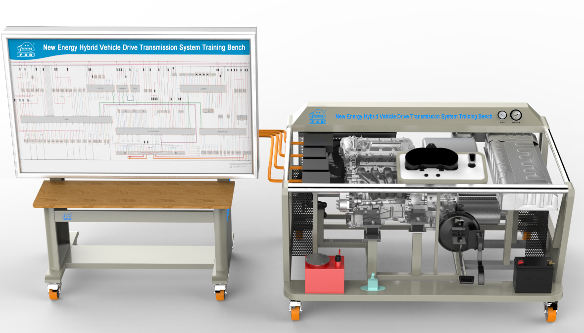
The device is made of the original hybrid power system of the new Toyota Corolla dual engine 1.8L new energy hybrid vehicle, equipped with the original 1.8L Atkinson cycle engine and E-CVT system. The hybrid power system can be started and operated through the original one button start system, gear control system, braking mechanism and acceleration mechanism.
The training bench is equipped with a half-shaft drive device, which can realize the real demonstration of working conditions such as hybrid system warm-up, pure electric drive, parallel hybrid drive, engine direct drive, energy recovery, starting, medium speed, and high speed.
The training bench is equipped with an OBD diagnostic interface, and a special diagnostic instrument can be used to read the fault code, read the data stream, clear the fault code, and test the components of the relevant electronic control system.
The training bench is equipped with a wireless intelligent fault setting module, which can be used to set faults such as open circuit, virtual connection and short circuit for the electronic control system circuit, actuator circuit and sensor circuit through a mobile phone or tablet computer. The fault setting method is reliable.
The training panel is made of advanced aluminum-plastic plate with characteristics of not less than 4mm thick, corrosion-resistant, impact-resistant, pollution-resistant, fire-resistant, and moisture-resistant. The surface is treated with a special process of spraying primer. The circuit diagram of the hybrid system is painted by UV inkjet technology on the panel, and detection terminals are installed on the controller, sensor, and actuator circuit, which is convenient for students to measure voltage, current, waveform and resistance.
Through the dedicated wiring harness, the training bench is connected in parallel with the detection panel, and the control logic diagram of each system of the training bench is painted on the detection panel. According to the panel control logic diagram and combined with the training platform, comprehensive training and troubleshooting are carried out to improve the students' ability to analyze and handle the faults of the hybrid system, which is applicable to the teaching needs of secondary and senior vocational skill schools, normal education and training institutions for the integration of vehicle theory and practice.
ii. Features
1. The main components are installed on the bench, and the electrical connection method is the same as that of the real vehicle. It can be easily disassembled after power failure, so that students can master the disassembly and assembly points and safety protection of high-voltage system components during the disassembling and connecting process (according to the overall wiring requirements, some fuses and relays were moved to the corresponding racks).
2. The training bench is equipped with pointer fuel pressure gauge and vacuum pressure gauge to display fuel pressure and vacuum pressure in real time.
3. Light-emitting diodes are installed on the training bench to display the working dynamics of the 4 injectors and relays in real time.
4. With the help of the original factory data, fully describe the functions and pin definitions of the main components on the device.
5. The training bench is equipped with an accelerator pedal and a gear shifter. The acceleration function can be realized by stepping on the accelerator pedal, and the forward D gear, reverse R gear, and S gear can be forced to recover the braking energy by operating the shift lever.
6. The training bench is equipped with installation protection devices such as the main power switch, water tank protective cover, and output shaft protective cover.
7. The detection panel completely displays the connection logic diagram of the hybrid system and the engine control system, and installs the detection terminals. With the help of the multimeter and the oscilloscope, the parameter changes under various conditions can be detected in real time.
8. The training bench is welded and assembled with high-strength carbon steel. After the carbon steel has been derusted, the exterior is painted with high-temperature electrostatic powder spraying. Four casters are installed at the bottom of the training table, which can move flexibly. At the same time, the casters have self-locking devices. Position can be fixed.
9. An emergency power-off switch is equipped with the training bench. Press the red button in an emergency, and the entire high-voltage power supply of the one-stop teaching system will be cut off. To ensure the safety of the teaching process.
10. Equipped with a control panel, which is located in front of the bench for easy operation. The accelerator pedal and brake pedal are located directly below, and the operation method is the same as that of the real car. At the same time, the OBD interface is moved to the control panel, which is convenient for data stream reading and fault detection.
11. The distribution and installation of each system of the training bench, cooling water tank, cooling fan, engine assembly, DC-DC inverter assembly, motor and E-CVT transmission system, etc., are similar to the installation position of the actual vehicle, and the training bench is convenient for students observing and learning from multiple perspectives, making the system connection and control relationship clearer.
12. Equipped with a wireless intelligent fault setting module, the teacher sets the fault, the students analyze and find the fault point, and master the fault handling ability of the real vehicle.
1. Engine 2. Transmission input damper assembly 3. MG1 4. Compound gear unit 5. Sun gear 6. MG2 7. Oil pump 8. Ring gear 9. Gear stand 10. Intermediate shaft driving gear (compound gear) 11. Deceleration driving gear 12. Intermediate shaft driven gear 13. Deceleration driven gear 14. Differential gear mechanism
iii. Basic Parameter
1. The external working power supply of the equipment: 220V AC, the power is not more than 1.4KW
2. Equipment working temperature: -20°~+40°
3.Dimensions of the main frame (mm): not less than 1800*1300*1100 (length*width*height)
4. Dimensions of the test stand (mm): not less than 1600*700*1730 (length*width*height)
5. Transmission: E-CVT
6. Engine model: 8ZR-FXE
Cooling method: water cooling
Maximum horsepower: 99PS
Maximum power: 73KW
Maximum torque: 142N.m
Engine-specific technology: VVT-i
Fuel Type: Hybrid
5. Motor type: permanent magnet/synchronous
Total motor power: 53KW
Total electromechanical torque: 163N.m
Working voltage: DC 650V
Cooling method: water cooling
6. DC-DC inverter assembly (DC-DC converter, boost converter, high voltage distribution box, motor controller)
Cooling method: water cooling
DC rated output voltage: 13.5-15V
DC/DC power: 1.5KW
Control module: IGBT (6 pcs)
Boost converter inverter side: DC650V
Boost converter HV battery side: DC201.6V
Protection class: IP67
iv. Basic Configuration
1 set of engine system assembly, 1 set of motor + gearbox system assembly, 1 set of DC-DC inverter, 2 sets of drive shafts, 2 sets of knuckle with brake disc assembly , 1 set of accelerator pedal, 1 set of brake system assembly, 1 set of instrument assembly, 1 set of electronic shifter, 1 set of one key start system, 1 set of gateway module, 1 set of power management control module, 2 safety covers, 1 set of cooling system, 1 12V55AH maintenance-free battery, 1 movable platform and teaching board, 1 wireless fault setting system motherboard, 1 AC220V to DC12V29A switching power supply, etc.