

i. Features(FXB-X19060)
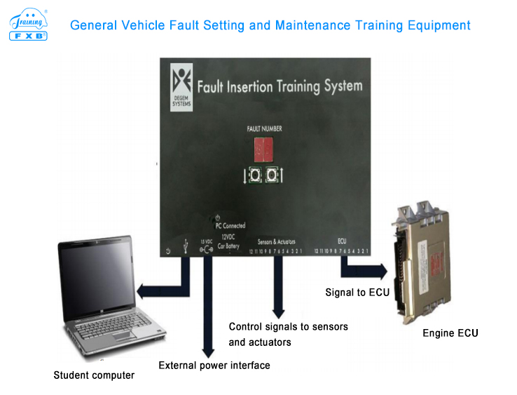
1. The fault setting maintenance training system can insert faults and maintenance without any real vehicle modification and damage in real vehicles through high-tech and unique methods. Modern cars use an electronic equipment control unit (ECU) to control the operation of the engine: fuel injection pulses, ignition timing, oxygen sensor (O2), coolant temperature, intake air temperature, etc. By inserting an open circuit at any signal line near the ECU, or disconnecting the ECU from the sensor signal line, or connecting the ECU signal input terminal to the ground or + 5V, several different faults that are not harmful to the real vehicle can be inserted.
2. This fault setting system can insert 8 independent faults into 8 different sensors and actuators. It uses normally open (N.O.) contacts to insert open circuit or normally closed(N.C.) contacts to disconnect the sensor or actuator, connect to the chassis, or connect to a preset voltage. In addition, 4 additional groups of sensors and actuators can be set to 19 faults by inserting open circuit, inserting chassis short circuit, inserting preset voltage, etc.
3. A spare OBDII scanner can further help students locate which system is faulty. The AT-6000 is intentionally designed to allow teachers to insert faults or correct faults themselves, without the need for factory engineers to go to the scene to modify. Once the model and vehicle chassis number is known, the factory technician will recommend setting up the 27 faults and provide the corresponding technical information. For example, the manufacturer's workshop manual for the specific vehicle selected by the training institution, and the AT-6000 fault insertion kit provides the necessary wiring accessories, which allows teacher to modify faults in the future.
4.In order to connect the system to a real car, the wires connecting the ECU and 12 predetermined sensors and actuators (Modifiable) must be unplugged, and the system must be connected between the ECU and the sensors and actuators. The original connection can be restored by unplugging the two sets of 12 pin cables on the AT-6000 and then connecting the two 12 pin cables between the ECU, the sensor and the actuator.
5. After you have selected the vehicle to set faults, you can easily modify the computer courseware, allowing teachers to design faults and set the faults by themselves, and then let students repair it and carry out corresponding diagnostic procedures. And the courseware can easily insert and repair faults. And it also allows the teachers or students to disconnect the AT-6000 fault insertion system from the vehicle, so that the vehicle can operate normally without fault insertion. This bypass setting greatly simplifies the maintenance of the daily equipment and effectively improves the service life of the equipment. If the vehicle operates normally in bypass mode, but does not operate normally after connecting the AT-6000 system, then the AT6000 fault insertion system is faulty. If the vehicle does not work properly in bypass mode, the connection to the vehicle or the 12-pin cable is faulty.
6. Automatic vehicle identification system (Avis) is an intelligent identification system developed based on OBDII and different vehicle ECU control systems. And the accuracy of fault setting can be improved by adapting the vehicle data of different vehicle models. The device is a high-precision control device with small size and few interfaces, which is convenient for transfer.
7. If you want to disable the fault insertion system, just unplug the two 12-pin gray connectors and connect to the two 12-pin gray connectors of the ECU, and unplug the two 12-pin gray connectors and access the grey sensor connector. Then plug the ECU connector connected to the ECU signal wire into the sensor connector connected to the sensor wire. The fault setting is now bypassed by the bypass device and the vehicle can operate without the AT-6000 fault insertion system.
ii. Basic Parameter
1. AT6000 real vehicle fault setting and maintenance system
The fault insertion relay can control any of the 12 ECU signal lines. The device contains 12 relays with transfer contacts, which can be set to open circuit, short circuit and grounding of any wire harness. The unit is also capable of inserting 3 predetermined voltages to any of the four fault insertion relays. The unit is controlled by an application, which runs on a student computer, which requires official windows software.
The device consists of the following components:
1.1 Matching device connectors
1.2 USB data cable
1.3 External power supply 15V/2A, 115/230 VAC, 50/60 Hz
1.4 Power cord
1.5 Fault switch relay (12) for transfer contact (rated 4A)
2. Special ECU wiring bayonet
The connection interface contains the following components:
2.1 12 pin docking ECU departure harness special connector interface
2.2 12 pin special harness interface for docking sensor or actuator
2.3 Two 12-pin dedicated wire harnesses (2.5m)
2.4 Two 12-pin wire harnesses (with a female connector and a male connector) can be connected to the wire harness between the unplugged ECU and the sensor, length 0.5m
Note: The male connector cable must be connected to the ECU side and the female connector cable must be connected to the sensor and actuator side
2.5 Maximum allowable continuous current - 4A
2.6 Two buttons (increase the number of faults, decrease the number of faults) are used to select faults.
2.7 2-digit LED display shows the selected fault number
2.8 Bypass device
3. Connect the device
3.1 Two 2.5m long 12-wire cables are connected by 12 pins, which can be plugged into the ECU connector or the sensor connector on the AT-6000 module.
3.2 Two 0.5m long 12-wire cables connected by 12-pin connectors to the 12-pin cable of the sensor cable or the ECU cable of the AT-6000 module
3.3 Each set of wiring harnesses (described in item 2) consists of a 12-pin wiring harness, terminal pins, signal wires from the ECU and signal wires to the sensors and actuators.
It makess the ECU end of each selected signal line of the ECU to be easily connected to the cable and makes it easy to plug the cable into the 12 pin ECU connector on the AT-6000.
4. Digital Multimeter
Equipped with digital multimeter of AT-6000. The selected insertion fault signal wire can be identified by measuring the resistance between the ECU cable connector and the signal wire cutting position. And the installation colors of all ECU signal wires are usually listed in the manufacturer's workshop manual.
The installer should attach test probes with alligator clips to the ECU connector terminals and pierce the wires with color-coded insulation where the wires were cut. This insulation corresponds to the color coding shown in the shop manual. Internal buzzer sounds if correct wiring is identified.
5. Automatic Vehicle Identification System (AVIS)
An intelligent identification system developed based on OBDII and different vehicle ECU control systems. By adapting different vehicle models to the corresponding vehicle data, the accuracy of fault settings is improved.
iii. Basic Configuration
AT6000 real vehicle fault setting and maintenance system, matching device connector, USB data cable, external power supply 15V/2A, 115/230 VAC, 50/60 Hz, power cable, fault switch relays for transfer contacts (12) (rated 4A) , multimeter, experimental course software system, automatic vehicle identification system, 1 laptop.