


It can realize the cognition of the high-voltage structure of the electric vehicle motor drive system and the learning of the control principle of the motor drive system. High-voltage interlock function training, high-voltage power-on, power-off operation training, three-phase current detection of the motor during charging and discharging. Common fault setting and troubleshooting of motor drive system, learning and troubleshooting of electronic accelerator pedal working principle, learning and troubleshooting of P gear controller, working principle learning and troubleshooting of intelligent key controller.
ii. Features
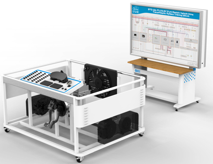
1. Select BYD Qin PLUS-EV pure electric vehicle motor drive system (vehicle date is October 2021 or later), install it on the bench without changing the relative layout of the original vehicle, and intuitively recognize the high-voltage power distribution assembly , three-in-one electric drive assembly (including motor controller, drive motor and single-stage gearbox), vehicle controller, rear body module (including electronic parking), gear controller, combination instrument, cooling water tank, etc. parts. The low-voltage control line and the high-voltage power line are all original vehicle parts, the length is increased, the high-voltage power line is orange, plus a protective bellows, and a warning mark is added at the connection. It is strictly forbidden to plug and unplug any high-voltage power line when the power is on. To enable students to understand the components and connections of the motor drive system as soon as possible.
2.This training bench, power battery and management system training bench, air conditioning and heating training bench, electric steering assist EPS training bench, and body electrical system training bench have a total of 5 sets of equipment. It is a one-stop teaching system through a dedicated line connection. The CAN communication of the whole vehicle is connected through the gateway, so that the students can understand the advanced nature of the CAN communication network of the new energy electric vehicle and the detection method of the signal waveform.
3. The training bench is equipped with teaching board, which fully displays the working principle diagram of the motor drive system, and installs detection terminals. There are no less than 200 detection terminals. With the help of tools such as multimeters, real-time detection of parameter changes in various states.
4. The training bench consists of a platform and a teaching board. The platform is placed horizontally and the main components are installed. Four casters, two swivel casters and two directional wheels are installed at the bottom of the platform, which can move flexibly. At the same time, the swivel casters have a self-locking device, which can fix the position. The casters have low rolling resistance, quietness and wear resistance, and the outer diameter is not less than 5 inches. The teaching board is installed on an alloy steel base, and four casters are also installed, which can be moved independently.
5. The training bench is equipped with standard DC fast charging and AC charging ports. The AC charging port supports 220VAC slow charging and is equipped with a 220V portable AC charging cable. Note that the ground wire must be connected reliably.
6. The training platform is equipped with an emergency power-off switch. The emergency power-off switch is installed in the easy-to-operate part of the control panel. Press the red button in an emergency, and the entire one-stop teaching system will be powered off. Ensure the safety of the teaching process.
7. The cooling fan and water tank are installed in front of the bench, which is the same as the actual vehicle position. At the same time, the hot air blowing out will not cause harm to the students' operation.
8. Increase the control panel, located on the right side of the bench, the accelerator pedal and the brake pedal are located directly below, the operation method is the same as the real vehicle. At the same time, the OBD interface is moved to the control panel, which is convenient for data flow reading and fault detection.
9. A load device is installed at the output end of the transmission shaft to simulate the vehicle load system. By adjusting the load size at both ends, the current and voltage and other parameters change rules of the electric drive transmission system under different working conditions (starting, acceleration, uniform speed, deceleration, half-slope starting, etc.) are truly reproduced. The load device and the original vehicle brake are flexibly connected by a V-shaped multi-ribbed belt, and there is an overload protection device to ensure that the load device does not vibrate when it is overloaded and slips.
10. Equipped with an intelligent fault setting and assessment system. Through the wireless fault setting of the mobile phone WIFI, the fault is set by the teacher, and the students analyze and find the fault point, and master the fault handling ability of the real vehicle. Wireless faults should be set to no less than 16 points, broken circuits, and occasional phenomena.
11. It can realize high-voltage structure cognition and test training of electric vehicle motor drive system.
12. It can realize the training and troubleshooting of the high voltage interlock function of the electric vehicle motor drive system.
13. Equipped with a special clamp meter for new energy vehicles and a high-voltage test pen, which are used to control line voltage, current and other parameter measurement and orange high-voltage loop high-current non-contact measurement.
14. The bottom frame of the training platform is welded with alloy steel profiles, which are strong and reliable, and the size of the main material is not less than 40*40mm. The upper part is protected by stainless steel handrails at the front and rear. The rotating parts on both sides are added with mesh plates to ensure the safety of the use process.
15.Supporting the standard new energy electric vehicle special AC charging connection device, the input power is 220VAC-50/60HZ-8A, the input end is connected to the 16A three-hole socket, and the cable specification is not less than 3*1.5+1*0.75; Vehicle docking, 7-core slow charging gun head, with CC, CP detection function.
16. Supporting embedded new energy vehicle drive system teaching resource package software V1.0. Explain the structural composition and control principle of mainstream new energy vehicle charging and distribution assemblies with 3D animation, including the following knowledge points:
16.1 Introduction: installation location, function, working parameters, characteristics
16.2 Introduction of external connectors: introduction of four orientations + top interface
16.3 High voltage distribution box: structure introduction, circuit diagram, optocoupler sintered sensor, sensor circuit diagram
16.4 DC-DC Converters: Introduction to DC-DC, Circuit Diagram, Working Principle
16.5 OBC vehicle charger: OBC introduction, circuit diagram
16.6 Connector pins
iii. Basic Parameter
1. Motor drive system:
Motor Type: Permanent Magnet Synchronous Drive Motor
Motor continuous power: not less than 35KW
Motor peak power: 100KW
Motor continuous torque: not less than 70N.m
Motor peak torque: 180N.m
Cooling method: water cooling
Transmission: Electric vehicle single-speed transmission
2. The external working power supply of the equipment: 220V AC, the power is not more than 3.3KW
3. Equipment working temperature: -20°~+40°
4. Dimensions of the main frame (mm): not less than 1800*1300*1100 (length*width*height)
5. Dimensions of the test stand (mm): not less than 1600*700*1730 (length*width*height)
iv. Basic Configuration(Unit)
High-voltage three-in-one charging and distribution assembly (including DC/DC converter, on-board charger OBC and high-voltage distribution box PDU), Vehicle controller assembly, EPB electronic parking controller, AC charging port, DC charging port, Gear controller, Instrument cluster, Start up button, Brake pedal assembly, Electronic accelerator pedal, Drive system three-in-one (drive motor, motor controller, reducer), Drive shafts, Brake discs, Flexible multi-ribbed belts, Magnetic powder brakes, Manual tension controllers, Safety covers, Cooling system, Hydraulic brake system, 12V55AH maintenance-free battery, Orange high voltage power lines, Low-voltage control lines, Special clamp meter for automobiles, High voltage test pen, Movable platform and teaching board.
V. Training project
Training task 1: The fault setting and troubleshooting experiment that the data communication signal line of the motor control system disconnection cause the vehicle to fail to run.
Training task 2: The fault setting and troubleshooting experiment that the brake switch signal line disconnection cause the whole vehicle to fail to connect the low-voltage power.
Training task 3: The fault setting and troubleshooting experiment that the data communication signal line of the vehicle controller unit system disconnection cause the whole vehicle to fail to connect the high-voltage power.
Training task 4: The fault setting and troubleshooting experiment that the high-voltage interlock signal line disconnection cause the whole vehicle to fail to connect the high-voltage power.
Training task 5: The fault setting and troubleshooting experiment that the IG3 relay control signal line disconnection cause the whole vehicle to fail to connect the high-voltage power.
Training task 6: The fault setting and troubleshooting experiment that the signal line of the electronic parking control switch disconnection cause the electronic parking to not work properly.
Training task 7: The fault setting and troubleshooting experiment that the signal line of the gear control system disconnection cause the fail to shift gear and drive normally.
Training task 8: The fault setting and troubleshooting experiment that the accelerator pedal signal line disconnection cause the failure to drive normally.
Training task 9: The fault setting and troubleshooting experiment that the signal line of the combination meter system disconnection cause the combination meter to fail to open normally.
Training task 10: The fault setting and troubleshooting experiment that the chassis network line disconnection cause the vehicle to fail to diagnose faults.