


Automotive Sensors Measurement and Training System
About
Feature
Technical Parameter
Basic Configuration
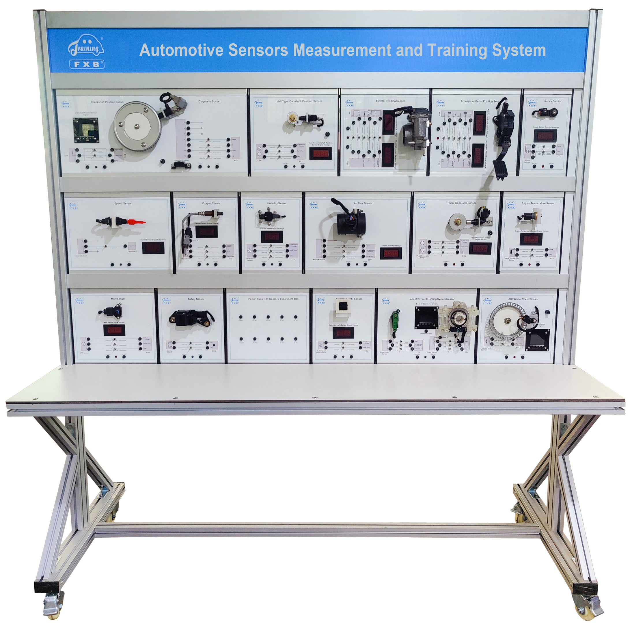
It’s designed based on various automotive sensors to demonstrate the composition and working process of sensors.
1. It adopts the original automotive sensors and installs them on the panel.
2. Each sensor module comes with related circuit diagram, students can learn and analyze the working principle by referencing the diagram and real sensors.
3. Each sensor module comes with detection terminals, students can measure electric signals by multimeter.
4. Each sensor module is equipped with fault-setting switches, for setting open circuit and poor contact faults.
5. It’s installed with OBD II diagnostic socket for reading the static data.
6. It’s equipped with voltmeter, frequency meter and oscilloscope for displaying the voltage, frequency and waveform changes of the sensors.
7. It requires 220V AC power supply, which is automatically converted into 12V DC for panel use, and 12V DC power supply protects the panel against short circuit.
8. It includes the following sensors: Crankshaft Position Sensor, OBD II Diagnostic Socket, Hall Type Camshaft Position Sensor, Throttle Position Sensor, Accelerator Pedal Position Sensor, Knock Sensor, Vehicle Speed Sensor, Oxygen Sensor, Humidity Sensor, Air Flow Sensor, Pulse Generator Sensor, Engine Coolant Temperature Sensor, Manifold Absolute Pressure Sensor, Safety Sensor, Automatic Light Sensor, Adaptive Front Lighting System Sensor, ABS Wheel Speed Sensor.
1. Dimension: 1900mm × 800mm × 2000mm (length x width x height)
2. External power supply: AC 220V±10% 50/60Hz
3. Operating voltage: DC 12V
4. Operating temperature: -40℃ ~ +50℃