

The engine calibration test bench applies the same development as that applied by most domestic OEMs, main engine plants and electronic control system suppliers so that the students can have the latest technical experience in a timely manner and acquire the abilities to apply related development environment in the process of learning. Students accomplishing this teaching module can seamlessly start their careers by working in related OEMs, main engine plants and electronic control systems, as well as various engine parts production suppliers.
This engine calibration test bench is mainly designed for the undergraduate students of automotive related majors so as train talents such as test equipment operators, test engineers, calibration engineers and product engineers.
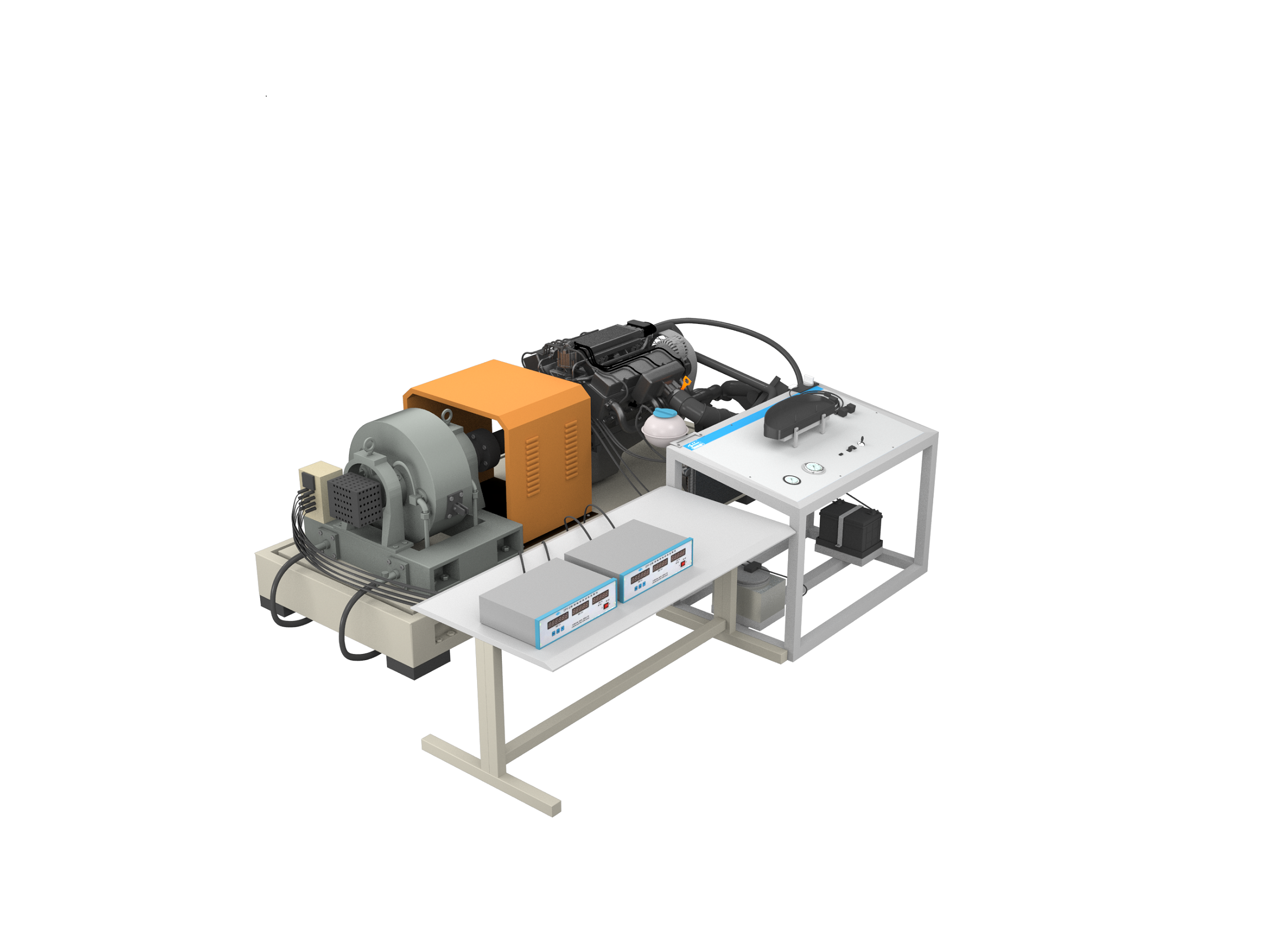
1)Real and operational electronically controlled gasoline engine is applied for this test bench. The dynamometer applies a load to the electrically controlled gasoline engine so that engine can work under different working conditions.
2)The engine is connected to a high-power eddy current dynamometer through a flexible shaft. The dynamometer is designed with components and parts such as high-precision torque speed sensor (accuracy: torque ± 0.2% FS, speed ± 1rpm), torque power speed measuring instrument, and load controller. It monitors the power and torque characteristics of the engine through dynamometer information and applies the load.
3)Two ways are applied to realize the control and acquisition of the eddy current dynamometer system: 1) through the torque speed power acquisition instrument and program-controlled loading controller; 2) through the host computer software for acquisition and control loading.
4)Mitsubishi's 4J15T National-VI Standard engine is applied for the test bench. It is a supercharged engine that can complete the main test contents under GB/T 18297 Engine Performance Test such as start-up test, idle speed test, power test, load characteristic test, universal characteristic test, oil consumption test, etc. .
5)Open ECU is applied for the engine, allowing students to modify and calibrate various parameters of engine management according to the own demands. In addition, a new calibration program can be written into the ECU so that the engine can run under preset conditions. Therefore, students can combine theories with practices and verify their control logic and theory through experimental data.
6)The engine performance is calibrated by the universal host computer calibration software applied in domestic and foreign automobile OEMs. . Through the calibration software, students can control and adjust engine operating program parameters for the purpose of calibration.
7)The engine is installed with sensors of various types and can detect, store and process the signals of each sensor and actuator through the host computer software, and process and analyze the performance characteristics of the engine. It can further improve and optimize engine ECU parameters based on analysis results to achieve desired engine performance indicators.
Hardware:
Upper computer laptop, CAN communication device, Development ECU
Online modification of calibration data,
Software:
Upper computer ECU data calibration operation log software
Upper computer ECU data analysis software
ECU address file, to be loaded to the upper computer INCA software for calibration operation
ECU data file, to be flashed to ECU, and loaded to upper computer INCA software with A2L file for calibration operation