

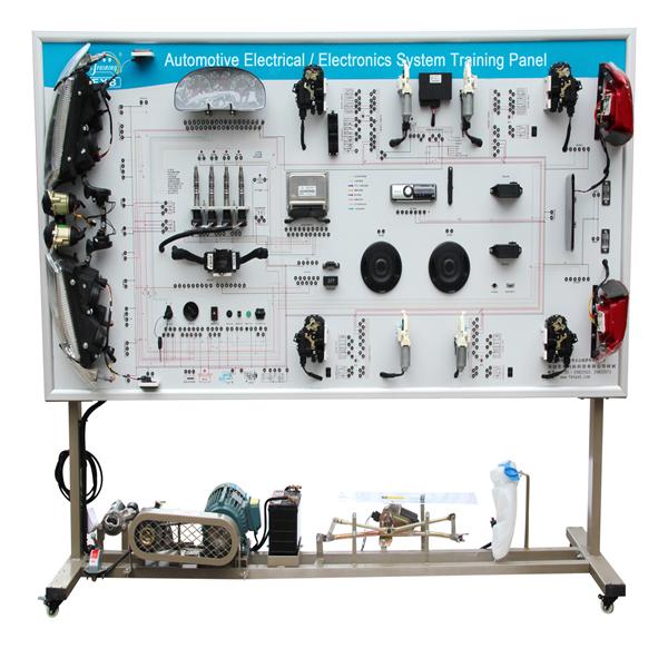
The device is designed based on the electric equipment system of the finished Volkswagen santana 2000 to holistically demonstrate structures and operation of the meter, lighting, wiper, horn, ignition, electric window, electric door lock, sound, startup, and charging systems. It applies to the teaching of automobile electric equipment theories and maintenance practicing in secondary and senior vocational skill schools, normal education and training institutions.
ii.Features
1.A real and operable electric equipment system is used to illustrate the structure of the system.
2.After the electric equipment system is powered on, switches and buttons of various electric equipment can be operated to
demonstrate operation of the meter, lighting, wiper, horn, ignition, electric window, electric door lock, sound, startup, and
charging systems.
3.The training panel is made of advanced aluminum-plastic plate with characteristics of not less than 4mm thick, corrosion
resistance, impact resistance, pollution resistance, fireproof, and moistureproof. Its surface are processed by special craft
and spraying primer. Never fade color circuit diagram and working principal diagram are painted on the board whose
surface coating with varnish. The trainees can learn and analyze the working principle of the control system by referencing
the diagram and the real object.
4.The training panel is installed with detection terminals to detect electric signals, for example, resistance, voltage, current,
and frequency, of circuit components of the electric equipment system of the finished automobile.
5.The training panel is installed with a diagnosis socket ,which can connect to automobile decoder to read fault codes reads
fault codes, clears fault codes, and reads data stream from the engineer control unit (ECU).
6.The training panel's base frame is made of steel and the surface is paint-coated. Self-retention wheels are installed.
7.Equipped with intelligent fault setting and appraisal system, include fault setting, troubleshooting and assessment
functions etc.
iii.Basic Parameter
1.Size: 2400mm × 700mm × 1900mm (length x width x height)
2.Driving power supply: three phase four wire (three phase five wire380 ± 10% V 50 Hz)
3.Operating voltage: 12V DC
4.Operating temperature: -40℃ to +50℃
5.Three-phase asynchronous motor
◆ Model: YT 100L1-4
◆ Voltage: AC 220V/380V
◆ Power: 2.2 KW
◆ Rotation speed: 1420 r/min
Basic configuration (unit)
|
No. |
Name |
Specification and model |
Unit |
Quantity |
|
1 |
Panel on the training platform |
With various detection terminals and connection plugs of the circuit terminal |
Set |
1 |
|
2 |
Engineer control unit (ECU) |
|
Set |
1 |
|
3 |
Diagnosis socket |
OBD II |
Unit |
1 |
|
4 |
Ignition switch |
|
Unit |
1 |
|
5 |
A full set of meters |
|
Set |
1 |
|
6 |
Switchgroup |
|
Set |
1 |
|
7 |
Front, left and right headlights assembly |
|
Set |
1 |
|
8 |
Left and right fog lights |
|
Set |
1 |
|
9 |
Left and right turn signal lights |
|
Set |
1 |
|
10 |
Left and right turn signal side lights |
|
Set |
1 |
|
11 |
Left and right combination taillights |
|
Set |
1 |
|
12 |
Number-plate light |
|
Set |
1 |
|
13 |
Reading light |
|
Set |
1 |
|
14 |
Switch for headlight |
|
Set |
1 |
|
15 |
Switch for fog light |
|
Set |
1 |
|
16 |
Switch for the brake light |
|
Set |
1 |
|
17 |
Switch for the back-up light |
|
Set |
1 |
|
18 |
Switch for door control light |
|
Set |
1 |
|
19 |
Harness |
|
Set |
1 |
|
20 |
Flash relay |
|
Unit |
1 |
|
21 |
Wiper assembly |
|
Set |
1 |
|
22 |
Wiper relay |
|
Unit |
1 |
|
23 |
Washer pump |
|
Set |
1 |
|
24 |
Sprayer |
|
Set |
1 |
|
25 |
Horn |
|
Unit |
2 |
|
26 |
Horn relay |
|
Unit |
1 |
|
27 |
X contactor relay |
|
Unit |
1 |
|
28 |
Fog light relay |
|
Unit |
1 |
|
29 |
|
Set |
1 |
|
|
30 |
Center relay box |
|
Set |
1 |
|
31 |
Meter signal simulator |
|
Set |
1 |
|
32 |
Starter assembly |
|
Set |
1 |
|
33 |
Generator assembly |
|
Set |
1 |
|
34 |
Three-phase asynchronous motor |
YT 100L1-4 |
Set |
1 |
|
35 |
Non-distributor grouping ignition system |
Including a crankshaft position sensor, an igniter assembly, and a spark plug |
Set |
1 |
|
36 |
Crankshaft position sensor and signal wheel |
|
Set |
1 |
|
37 |
Accumulator |
46B24SR, 12 V 45 Ah, and 550 CCA |
Set |
1 |
|
38 |
Master power switch |
50A |
Unit |
1 |
|
39 |
Intelligent fault-setting and appraisal system |
FXB-688 |
Set |
1 |
|
40 |
Movable framework (with self-retention wheels) |
1700mm × 1100mm × 800mm (length x width x height) |
Set |
1 |