

1. Select mainstream pure electric vehicle power battery packs, lithium iron phosphate power batteries, single cell batteries of 3.2V50Ah, a total of 24 series sections, and a total voltage of 76.8V. Distributed battery management system, with 2 collection modules, each responsible for collecting 12 individual battery information, and 1 main control module. The main control module communicates with the 2 collection modules through the CAN network. The power battery pack, as a basic configuration, outputs high-voltage electricity to different electric drive system training platforms, enabling students to master the most advanced power battery pack technology.
2. The power battery pack is equipped with a detection port, which can measure the individual battery and battery PACK voltage. The discharge relay, charging relay, pre charging relay, and Hall current sensor are equipped with detection ports, which can measure the on-off of the control power supply. Enable students to master the ability to detect actual vehicle parts.
3. The BMS battery management system information of the power battery pack is displayed on a 10 inch LCD display screen through RS485 communication. The display screen is touch controlled and can display real-time voltage of each power battery, real-time temperature at multiple monitoring points, discharge relay working status, charging relay working status, pre charging relay working status, bus current size and other battery pack information.
4. The power battery pack is equipped with a mechanical maintenance switch to facilitate cutting off the entire power supply.
5. The mechanical maintenance switch, power battery output interface, and power battery charging interface are all equipped with high-voltage interlocking circuits to ensure the safety of not being powered on if the strong current interface is not installed in place.
6. The output line of the power battery pack is equipped with a mechanical disconnect emergency switch, which is suitable for easily disconnecting the main power circuit in emergency situations.
7. The power battery pack features a semi transparent design and built-in LED lighting, making it easy for students to observe the internal structure of the battery.
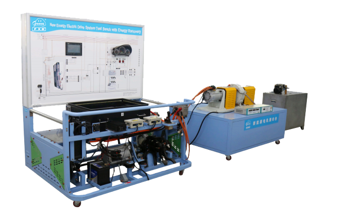
8. The training platform is equipped with mainstream pure electric vehicle single speed transmissions, transmission shafts, and brake assemblies. The brake assembly drives the real load device through flexible transmission, and the load size can be adjusted separately to reproduce the actual working conditions of the vehicle, such as downhill, flat road driving, uphill driving, half slope starting, turning driving, etc. Enable students to grasp the changes in current and voltage parameters under actual working conditions.
9. The training platform is equipped with a pure electric vehicle electric vacuum assistance system, making braking operation easier. The vacuum tank is made of all stainless steel structure, and the pressure sensing switch is a sensor structure, with a lifespan of more than 100000 times.
10. The training platform is equipped with a 12V power grounding mechanical switch, which can disconnect the 12V grounding at any time and cut off the entire system power supply.
11. Install 4 casters at the bottom of the training platform, which are flexible in movement. At the same time, the casters are equipped with self-locking devices, which can be freely fixed in the installation position.
12. The base of the training platform is welded with alloy steel structure, which is sturdy and shockproof. Install protective devices on both sides to ensure safety during use.
13. The training platform is equipped with an aluminum alloy teaching board, clearly marked with the composition and control principle of the power battery pack PACK. The teaching board material is 4mm fully conductive aluminum plastic board, and the surface is laser sprayed, never changing color. Testing terminals are used for the installation of teaching boards, and real-time detection of parameter changes in various states is carried out using a multimeter and oscilloscope.
14. The training platform is equipped with an intelligent fault setting and assessment system, which is set by teachers. Students analyze and locate the fault points. The fault phenomena are open circuit and occasional, and there are no less than 15 fault points related to the main faults of new energy vehicles. Master the ability to handle actual vehicle faults through troubleshooting communication.
15. Through CAN communication, fully display the operating process parameters of the power battery pack and motor controller on the 10 inch touch screen. When the motor speed exceeds 1000r/min and the brake pedal is pressed, the electric drive system begins energy recovery. The displayed parameters include throttle depth, motor speed, motor torque, controller temperature, motor temperature, bus terminal voltage/current, and output terminal voltage/current of the motor controller, which are used for energy recovery data analysis.
16. By using the signals of two driving motors and AC output high-voltage electric wire exchange connection, switching between the training platform and the test platform can be achieved.
17. In addition to the drive motor of the drive transmission system, an additional drive motor is equipped for torque power analysis. By adjusting the loading controller, the load size of the drive motor is accurately controlled to change the speed of the drive motor. At the same time, the torque, speed, and power of the drive motor are displayed for analyzing the torque curve of the drive motor.
18. Place the test bench horizontally, install driving motors, high-precision torque and speed sensors, high-power eddy current brakes, torque and speed measuring instruments, inertia discs, loading controllers, and other power measuring components.
19. The thickness of the bottom plate of the test bench are not less than 30 millimeters, and the structural strength shall be stable. Four casters shall be installed at the bottom, which can move flexibly. At the same time, the casters shall be equipped with self-locking devices, which can be fixed in position.
20. The test bench is equipped with a stainless steel water cooling device, which is used to cool and cool the high-power eddy current brake, ensuring the adjustment accuracy of the test bench.
21. The test bench is equipped with a torque and speed measuring instrument workbench, which is used to place precision components of the test bench.
22. Install a safety cover on the test bench to ensure safe operation.
23. The dynamometer is equipped with an inertia plate. When the accelerator pedal is pressed, the display screen displays the depth of the accelerator pedal, motor speed, motor torque, controller temperature, motor temperature, input DC bus voltage and current, and output AC voltage and current. Pressing the brake pedal, the motor inertia runs, and the mechanical energy is converted into three-phase AC power. It is then converted into DC power through the motor controller to feed back the power battery pack for charging. The specific parameters are displayed in real-time on the 10 inch touch screen.
1. Overall dimensions of the training platform (mm): 1600 * 1200 * 1800 (length * width * height)
Overall dimensions of the test bench (mm): 1600 * 1200 * 1000 (length * width * height)
2. Equipment working power supply: 220V AC, power not exceeding 2KW
Equipment working temperature: -20 ° to+40 °
3. Auxiliary battery: 12V45AH
4. Power battery type: environmentally friendly lithium iron phosphate power battery (square aluminum shell, single cell 3.2V50AH)
Power battery pack capacity: 76.8V50AH (3.8 kWh)
Complete charge and discharge frequency: 2000 times
Working temperature: -20 °~60 °
5. Motor controller: 72V300A (intelligent AC variable frequency control technology)
6. Drive motor: 72V5KW (AC variable frequency asynchronous motor)
7. Transmission: two-stage helical gear transmission, with a total reduction ratio of 1:10. Operating noise less than 70 decibels
8. Magnetic powder brake: PBS-50 (with adjustable tension controller)
Rated torque: 50N. m
Allowable speed: 1500r/min
9. Torque and speed sensor: ZJ-100A
Torque range: 100 N.m
Speed range: 6000RPM
Number of teeth: 60 teeth
Accuracy: torque ± 0.2% F.S
Speed ± 1rpm
10. Torque, speed, and power acquisition instrument: TS-3S (displaying torque, speed, and power. 485 communication)
11. Elastic coupling: polyurethane, plum blossom shaped
12. Eddy current brake: DWZ-16 dual shaft (70 N.m, 7000r/min, 6KW water cooled)
13. Loading controller: SC-1WS (power supply AC220V. output loading current 0-3A)
1 set of lithium iron phosphate power battery pack (including 24 individual cells, 1 discharge relay, 1 charging relay, 1 pre charging relay, 1 pre charging resistor, 1 Hall current sensor, 1 mechanical maintenance switch, 1 instant fuse, 1 charging interface, 1 discharge interface, 1 low-voltage control interface, 2 power battery acquisition modules, 1 BMS battery management system main control module, and 1 10 inch LCD display screen), 1 set of high-voltage charging cable, 1 set of high-voltage discharge wire, 1 set of low-voltage control wire, 1 on-board charger, 1 7-core national standard charging interface (with CC/CP signal), 1 220V national standard charging gun, 1 DC-DC converter, 1 motor controller, 1 electronic throttle assembly, 1 gear shifting mechanism assembly (with CAN communication), 1 AC asynchronous drive motor, 1 combination instrument (with CAN communication), 1 gearbox, 2 transmission shafts, and 2 front wheel disc brakes, 2 flexible multi wedge belts, 2 magnetic particle brakes, 2 manual tension controllers, 1 booster with pump assembly, 1 vacuum pump assembly, 1 vacuum tank assembly, 1 intelligent fault setting system, 1 auxiliary battery, 1 mechanical battery disconnect switch, 1 automotive special clamp watch, 1 high-voltage measuring pen, movable platform and teaching board. Power measuring drive motor, torque speed sensor, eddy current brake, inertia device, torque speed power acquisition instrument, loading controller, water cooling system.