

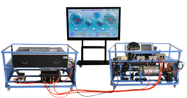
1. The integration of mainstream pure electric sedan electric drive transmission systems that are truly operational, fully showcasing the composition structure and logical control relationships of various main components.
2. Each main component is installed on a platform, consisting of two platforms, one for the power battery system and the other for the motor drive control system. The connection method of each component is the same as that of the actual vehicle, and the length of the connection line is extended.
3. Adopting mainstream electric vehicle cylindrical 18650 ternary lithium battery cells, with a single battery voltage of 3.65V and a capacity of 2.5AH. The PACK method adopts 12 parallel 92 series, with a total voltage of 3.65 * 92=335.8V, a capacity of 30AH, and a total power of 335.8V30AH (approximately 10 kWh).
4. The power battery pack 10-inch display (with touch function) and vehicle instrumentation are mounted on the operating panel. After pressing the accelerator, observe the various parameters of the vehicle's operating status, and master the control logic and main component parameter changes during the operation of pure electric vehicles.
5. By operating the upper computer software, the 10 inch display of the power battery pack can set some control parameters, which can be manually changed to reproduce the fault phenomenon. The parameter changes include high monomer voltage, low monomer voltage, large monomer pressure difference, low battery total voltage, and large battery temperature difference.
6. The power battery pack is fully transparent in design, and the upper cover is made of specialized insulation resistant transparent material, which clearly reproduces the structure of the battery module. The power battery pack is equipped with a dedicated detection port for voltage between 1-12 sections. Wearing insulated gloves can directly measure the voltage of individual batteries.
7. The power battery pack is equipped with a high-voltage interlock protection circuit, and any high-voltage connector that is not properly inserted cannot be powered on, ensuring the safety of the power battery pack when powered on.
8. The power battery pack is equipped with total positive, total negative, and partial voltage high-voltage high current relays, which are always in a normally open state when not powered on, to protect the safety of the measurement process after the student loses power.
9. The power battery management system adopts distributed battery management, with four acquisition modules installed in the power battery pack. Each acquisition module is responsible for collecting the voltage and temperature of 22-24 series groups. One main module is connected to the four acquisition modules using CAN bus. The upper computer program of the power battery pack can be provided to change some parameter settings through a 10 inch display screen.
10. The motor controller adopts the mainstream domestic pure electric vehicle universal permanent magnet synchronous AC controller, and the control element is an IGBT high-voltage high current module. Convert direct current into three-phase alternating current to drive the motor, and use a rotary signal to control the direction and speed of the drive motor and controller. The upper computer program of the motor controller can be provided to change some parameter settings.
11. The driving motor adopts the domestic mainstream pure electric vehicle permanent magnet synchronous motor. When the three-phase alternating current is connected to the stator coil, the rotating magnetic field will be generated, and the rotating magnetic field will pull the permanent magnet inside the rotor to generate the rotating torque synchronized with the rotating magnetic field. The drive motor does not use idle speed, and even when the vehicle is in a critical state from stationary to starting, it can generate maximum driving torque to ensure smooth operation.
12. Adopting the mainstream domestic pure electric vehicle star network structure VCU vehicle controller strategy. The VCU transmits data to the motor controller, power battery pack BMS, instruments, etc. through the CAN network. The signals of gear position, throttle, brake, water temperature, etc. are transmitted to the VCU through hard wire. After conversion, the VCU transmits the driving signal to the motor controller through the CAN network. The motor controller collects the driving motor rotary signal and converts the high-voltage direct current into three-phase alternating current to drive the vehicle.
13. Adopting high-speed pure electric vehicle single speed transmission, transmission shaft, and brake assembly. The brake assembly drives the real load device through flexible transmission, and the load size can be adjusted separately to reproduce the actual working conditions of the vehicle, such as downhill, flat road driving, uphill driving, half slope starting, turning driving, etc. Enable students to grasp the changes in current and voltage parameters under actual working conditions.
14. The system is equipped with two mechanical maintenance switches, one installed in the middle of the power battery and one installed at the power input end of the high-voltage distribution box to ensure safe use. In case of emergency, one can be disconnected. The power battery pack is fully transparent in design, with clear internal module layout. After pulling out the mechanical maintenance switch, the upper cover can be opened for observation. The high-voltage electrical connectors are all made of original components from BYD, BAIC, JAC, and other series.
15. The main high-voltage components control signal connectors are connected to measurement interfaces, and the connectors are the same as the actual vehicle, used for in-situ signal measurement by students, including power battery pack interface, onboard charger interface, high-voltage distribution box interface, motor controller interface, vehicle controller interface, DC-DC converter interface, etc.
16. There are various methods for erecting faults, including mechanical in-situ fault setting, upper computer software control BMS fault setting, and actual vehicle fault component fault setting, totaling three types of fault settings. No less than 30 mechanical failure points. Enable students to master the method of diagnosing real vehicle faults.
17. The training platform is equipped with an electric vacuum assisted hydraulic braking system, and the switch signal intelligently controls the intermittent operation of the vacuum pump through a pressure sensor.
18. The training platform is equipped with a 12V power grounding mechanical switch, which can disconnect the 12V grounding at any time and cut off the entire system power supply.
19. The training platform is equipped with safety protection devices such as brake protective covers.
20. The teaching board diagram fully displays the working principle diagram of the electric drive transmission system. The teaching board diagram is provided in an electronic version (equipped with 1 USB flash drive), which can be enlarged or reduced to clearly display the control principle of the entire vehicle.
21. The training platform is equipped with an emergency power off switch. The emergency power off switch is installed in the front of the power battery pack, which is easy to operate. In emergency situations, pressing the red emergency power off switch button will power off the entire high-voltage system, ensuring the safety of the teaching process.
22. Equipped with 3 parallel battery modules, it is used for learning the series variation rules of power batteries and practicing the PACK assembly of power batteries.
23. Equipped with 10 18650 single cell power batteries, used for voltage and internal resistance measurement exercises of single cell power batteries.
24. Equipped with two automotive specialized clamp gauges, used for measuring the insulation resistance of high-voltage connecting wires and the common terminal parameters of shielding wires.
25. Equipped with one insulation tester for high-voltage insulation performance measurement.
1. Overall dimensions of the power battery system (mm): not less than 1600 * 1300 * 1800 (length * width * height)
External dimensions of motor drive system (mm): not less than 1600 * 1300 * 1800 (length * width * height)
2. Equipment working power supply: 220V AC, power not exceeding 3.3KW
Equipment working temperature: -20 ° to +40 °
3. Auxiliary battery: 12V45AH
4. Power battery type: environmentally friendly ternary lithium power battery (cylindrical 18650, single cell 3.65V2.5AH)
Composition of power battery pack: 12P92S (each module has 12 individual batteries in parallel and 92 modules in series)
Power battery pack capacity: 335.8V30AH (approximately 10 kWh)
Complete charge and discharge frequency: 2000 times
Working temperature: 20 °~60 °
5. Motor controller:
Rated input voltage: 336V
Continuous current: 102A
Short time current: 300A
Power module: IGBT
Working system: S9
Protection level: IP67
Weight: approximately 50Kg
5. Drive motor: permanent magnet synchronous motor
Rated voltage: 312V
Continuous power: 30KW
Peak power: 60KW
Maximum speed: 9000RPM
Continuous torque: 82Nm
Peak torque: 250Nm
Insulation level: Class F
Cooling method: water cooling
Protection level: IP67
Working system: S9
Weight: approximately 50Kg
6. Transmission: Electric vehicle single stage transmission, two-stage helical gear reduction
7. Car charger: AC intelligent car charger
Rated input voltage: 220VAC
Rated output voltage: 360VDC
Rated output power: 3.3KW
Charging mode: Response mode
1 ternary lithium power battery pack, 1 on-board charger, 1 high-voltage distribution box, 1 DC-DC converter, 1 instrument panel, 1 charging port, 1 motor controller, 1 electronic accelerator assembly, 1 gear shifting mechanism assembly, 1 drive motor, 1 gearbox, 2 transmission shafts, 2 front wheel disc brakes, 2 belt drives, 2 magnetic powder brakes, 2 manual tension controllers, 1 booster with pump assembly, 1 vacuum pump assembly, 1 vacuum tank assembly, 1 auxiliary battery, 1 set of movable platform and teaching board, 3 battery modules, 10 individual batteries, 1 faulty accelerator pedal, 1 faulty high-voltage maintenance switch, and 1 pair of insulated gloves. One 70 inch intelligent mobile podium and one set of open data acquisition system.