

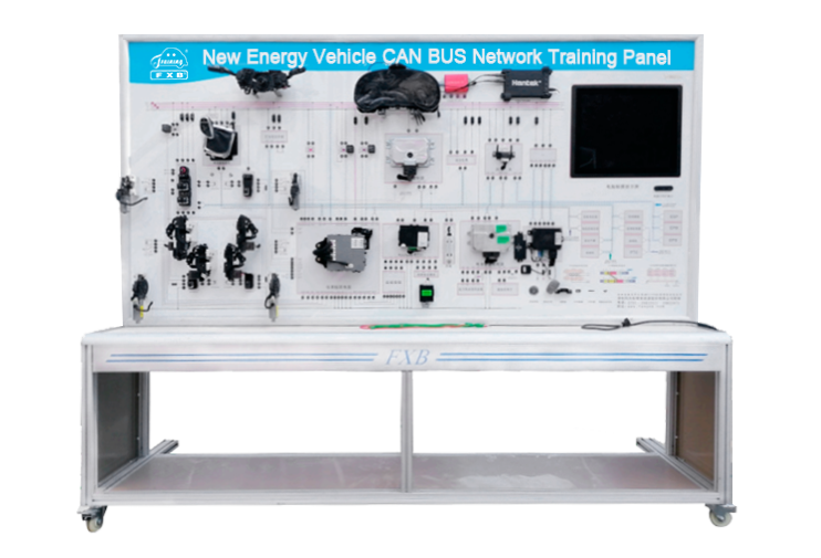
1. The data bus CAN-BUS system has complete components and fully displays the structural composition of the data bus CAN-BUS system.
2. The data bus CAN-BUS system is working normally and can demonstrate the working status of data bus data transmission in the power network, comfort network, ESC network, and startup network systems of the CAN-BUS system, fully demonstrating the working process and principle of the data bus CAN-BUS system.
3. The training panel is equipped with a computer integrated display, which can read and display various CAN bus analysis messages and data waveforms. It does not require an external oscilloscope to collect and analyze message data.
4. Students can visually compare the colored circuit diagram and working principle schematic diagram of the teaching board panel to learn the structural schematic diagram and physical object of the electric vehicle CAN bus network system, and understand and analyze the connection mode and working principle of the electric vehicle CAN bus network system.
5. There are detection terminals installed on the panel of the training platform, which can directly detect the electrical signals of the wiring pins of various electrical components in the CAN-BUS system, such as resistance, voltage, current, frequency, waveform signals, etc.
6.The training platform is equipped with a diagnostic seat that can be connected to a fault detector to perform self diagnostic functions such as reading fault codes, clearing fault codes, and reading data streams for the CAN-BUS system's electronic control system.
7.The training platform is matched with a 2-channel CAN analyzer, which can read and analyze each CAN network information and simulate system components sending CAN messages to the control BUS.
8.Adopting a DC12V power supply device to reduce the trouble of charging, the power supply has anti short circuit function.
9.The equipment adopts a mobile platform structure with locking universal casters, which is convenient for teaching. The overall platform adopts rigid structure welding using national standard materials. The surface is treated with high-end car paint spray molding and high-temperature baking treatment, which is moisture-proof, rust proof and durable.
10.Equipped with an intelligent assessment and examination system V1.0:
This system is based on the Android system and wireless network (WIFI), and designs an intelligent fault setting and assessment system as an APP software that can run on any Android smartphone or tablet. It utilizes the WIFI networking function of the phone or tablet to communicate wirelessly with a training platform or teaching board equipped with a remote fault setting control system module.
1. External power supply: AC 220V ± 10% 50Hz
2. Working voltage: DC 12V
3. Working temperature: -5 ℃~+50 ℃
4. Display size: not less than 19 inches.
5. Equipment dimensions: not less than 2400 × 700 × 1800mm (length × wide × High).
6. Teaching board size: not less than 2400 × 1200 × 200mm (length × height × thickness)
1. One left front window motor.
2. One right front window motor.
3. One left front lock block.
4. One right front lock block.
5. One left rear window motor.
6. One left rear lock block.
7. One right rear window motor.
8. One right rear lock block.
9. One combination instrument.
10. One gateway computer.
11. One window combination switch.
12. One button start switch.
13. One diagnostic seat.
14. One smart key control box (IK).
15. One high-frequency receiver.
16. One brake switch.
17. One instrument panel distribution box.
18. One 4G module.
19. One complete vehicle control module.
20. One battery management module.
21. One light combination switch.
22. One practical training panel.
23. One DC12 switching power supply.
24. One detection antenna.
25. 2 Channel CAN network analyzer 1 piece.
26. One dual channel oscilloscope.
27. One set of 19 inch computer all-in-one machine.