

1. Sensor system functions
1) Forward vision system: to achieve the detection, identification, tracking and other functions of environmental targets (including pedestrians, vehicles, traffic lights, traffic signs, lane lines, etc.).
2) LIDAR system: collects platform environment information to generate point cloud data for exercisable area detection and obstacles detection, and can get three-dimensional information of obstacles.
3) Surround view system: 360 degrees detect whether there are obstacles around and obtains the relative orientation and distance of obstacles, intuitive and without any blind spots.
4) Millimeter wave radar system: detects the distance and speed of forward obstacles, and tracking obstacles, with strong anti-interference capability.
5) Ultrasonic radar system: detects the location and distance of obstacles, processes the data, and complements with surround-view system.
6) IMU/GPS: Based on the known position information, IMU sensor calculates and gets the speed, position and attitude of the platform and get the new position location based on GPS information.
2. Battery and electronic control module functions
1) Battery system function: the main parameters of the battery can be read, including remaining power, real-time current, current voltage, current temperature, custom alarm information, etc.
2) Drive system function: Adopt wire-controlled drive system, the decision control unit can control the motor controller to execute acceleration, deceleration, energy recovery and other working conditions through CAN signal.
3) Braking system function: adopts motor reverse electric potential (brake during running), electromagnetic brake holding (brake during parking) function.
4) Steering system function: adopts Ackermann wire-controlled steering system, which can adjust the direction in real time according to the navigation path and obstacles position.
3. Identification and control module functions
1) Obstacles identification function: carry out fusion calculation through the detect data of LIDAR, camera and millimeter wave radar, then control the platform to safely avoid obstacles through calculation results to ensure vehicle driving safety.
2) Map construction function: LIDAR collects 3D environment information and combines with forward camera and GPS position information to construct a global map.
3) Positioning function: locate the platform's position information through the global map, real-time LIDAR point cloud information and IMU/GPS information.
4) Deciding and planning module: Based on the target state information and the current state information of the platform outputted by the perception and positioning module, and combined with the positioning role of the high precision map, to generate a collision-free, satisfying vehicle kinematics trajectory, and make decisions such as parking and detouring, containing location information of speed, acceleration and displacement.
5) Control execution module: control execution of the calculation input of the deciding and planning module, including the control of lateral left and right turns, control of longitudinal speed or parking control, etc.
4. Human-computer interaction function
1) Display: It can display the information of surrounding environment of the vehicle as well as the vehicle driving information including speed and acceleration, etc. The vehicle can be operated by touch screen, such as stopping and starting, etc.
2) Keyboard: connected to the vehicle computer by wireless, then commands can be input, and debugging of modules, system debugging and control.
3) Remote control handle: connected to the vehicle by wireless, the remote control operation mode can be switched, including starting, stopping, accelerating, steering, etc.
4) Terminal equipment: equipped with a laptop computer, the self-driving development platform software is installed. It’s connected to the vehicle computer through the communication line, to carry out vehicle maintenance, debugging and development and verification work tasks.
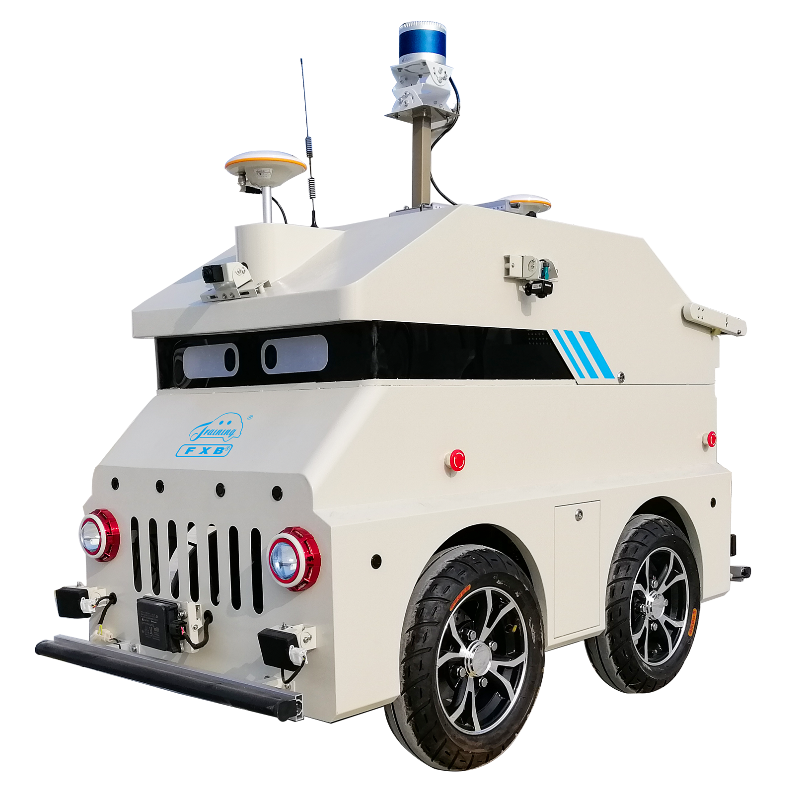
1. Parameters of the whole vehicle
Overall dimension (mm): not less than 1200 × 700 × 900 (length × width x height)
Minimum turning radius: 2.0m±0.1m
Wheel base: 0.66m
Wheel track: 0.606m
Maximum speed: not more than 10km/h
Maximum climbing gradient with full load: 30%
Wire-controlled drive / brake system:
Drive mode: rear drive
Control mode: torque
Rated power: 0.5kW
Rated voltage: 48V
Rated speed: 3000rpm
Speed feedback error: ±0.1 m/s
Wire-controlled steering system:
Control mode: speed/torque/position
Rated power: 220W
Rated voltage: 24V
Response time: <100ms
Control accuracy: ±1°
2. Power battery system
Form: automotive grade lithium battery
Rated voltage: 48V
Rated current: 20A
Capacity: ≥2kWh
Battery box waterproof level: IP67
3. BMS system
Over-charge, over-discharge, short-circuit, high temperature protection, etc.
Communication interface: CAN
Power supply interface: 24V 20A, 12V 25A, 12V 20A, 5V 10A
4. LIDAR
16 lines and above LIDAR, accuracy not less than ±2cm, vertical angle resolution not more than 2 degrees, safety protection level not less than IP67
Distance measurement: 20cm to 150m (target reflectivity 20%)
Viewing angle (vertical): ±15 degrees
Viewing angle (horizontal): 360 degrees
Angular resolution (horizontal/azimuth): 0.09 degree (5Hz) to 0.36 degree (20Hz)
Rotational speed: 300/600/1200rpm (5/10/20Hz)
5. Millimeter wave radar
Transmitting frequency band at 76-77Hz, with both medium and short distance scanning capability, coverage distance greater than 1-175m, horizontal viewing angle greater than ±45 degrees, input voltage DC 8-16V.
It can match with the underlying control algorithm of vehicle, and play a important role in self-driving function of intelligent connected vehicles.
With multi-position mounting mechanism, can match with the training vehicle for installation and debugging.
We can set and calibrate the multiple key parameters for millimeter wave radar on the multi-sensor fusion wire-controlled chassis.
6. Camera
The camera is industrial grade and above.
Specific parameters of camera are as follows:
Lens type: fisheye
Photographic sensor: IMX291 (1/2.8 inch)
Maximum effective pixels: not less than 1280 (H) * 720 (V)
HDR range: >120dB
Interface type: Fakra Z
Power supply and interface: 5-12V Fakra Z socket
Voltage: DC 5V
Current: 150mA-200mA
1 set of 16-line LIDAR, 1 unit of forward camera, 4 unit of surround-view cameras, 1 unit of 77GHZ millimeter wave radar, 1 set of combined inertial navigation system, 8 unit of ultrasonic radar, 1 unit of self-driving computing platform, 1 set of wire-controlled chassis (including VCU, wire-controlled steering system, wire-controlled braking system, wire-controlled motor driving system), 1 unit of 23.6-inch industrial display screen, 1 set of mouse and key integrated keyboard, 1 set of laptop computer.