


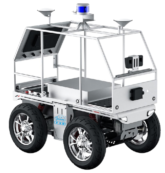
Apollo self-driving training platform adopts Apollo self-driving technology to develop. The training platform integrates wire-controlled chassis, LIDAR, millimeter wave radar, camera, combined inertial navigation and other environmental perception sensors, high-performance computing unit. It can realize RTK tracing, perception and obstacle avoidance, and other self-driving functions. The system covers wire-controlled, perception, prediction, planning, control and other knowledge points and applications related to self-driving. And it provides developer tools, which is suitable for intelligent connected vehicles (ICV) technology training needs.
ii. Features
1.Industrial integrated structure design, easy disassembly and assembly, convenient equipment debugging and troubleshooting.
2. Pure wire control design and integrated control are specially designed for autonomous driving. It provides full-vehicle CAN interface protocol and autonomous driving Apollo and other framework systems to support user secondary development and all-round capability training.
3. The vehicle body is equipped with 1 binocular high-definition camera, 8 automotive ultrasonic radars, and 1 77GHz millimeter-wave radar, which can achieve all-round obstacle avoidance through the automatic driving system, making driving safer.
4. Provide an operating manual for the autonomous driving kit.
5. Equipped with emergency stop switch, front and rear anti-collision bars, command verification, heartbeat protection, steering system fault handling, drive system fault handling, emergency power-off parking protection, battery fault monitoring protection, vehicle CAN node online detection, vehicle fault level classification and processing, vehicle fault alarm, vehicle sudden deceleration prompt, vehicle out-of-control protection, remote control disconnection processing, charging safety monitoring and protection, and the remote control distance is ≥100m.
6. It can complete the binocular camera calibration function, and can set the value of the left camera to the left edge of the front windshield, the value of the left camera to the right edge of the front windshield, the value of the distance between the outer edges of the two front wheels of the car, the value of the left camera to the ground, the value of the left camera to the front bumper, the value of the front of the car to the ground, target learning, parallax learning and other calibration functions.
7. It can complete the integrated navigation calibration function and configure the integrated navigation's own parameter calibration, including the calibration of the positioning antenna to the rear wheel center arm value, the calibration of the inertial navigation to the GNSS positioning antenna arm value, the inertial navigation system motion initialization configuration and other functions.
8. It can complete the LIDAR configuration and test function, and can use the upper computer software to configure and test the function of LIDAR.
9. It can complete the configuration testing function of millimeter wave radar, and can use the radar upper computer software to set parameters such as forward detection angle and detection target type
10. It can complete the configuration function of the computing unit, set the IP address between the computing unit and the sensor, view CAN network communication data, serial port, chassis, LiDAR point cloud, navigation signal and other data.
11. It can complete the verification of autonomous driving functions, including map collection and recording functions, tracking demonstration verification, obstacle parking demonstration verification, obstacle avoidance demonstration verification and other functions.
iii. Technical Parameters
1. Chassis and bracket
1.1 Overall dimension (mm): not less than 1320×765×1420 (L×W×H),including front and rear collision protection device and sensor bracket
1.2 Maximum speed: not less than 5km/h
1.3 Minimum distance from the ground: not less than 100mm
1.4 Minimum turning radius: less than 2000mm
1.5 Overall bridge type suspension, wheelbase 660mm, wheel track 645mm, tire diameter 420mm.
2. Power battery
2.1 Battery power: not less than 20AH
2.2 Charging time: less than 5h
2.3 Battery voltage: 48V
2.4 endurance: not less than 3h
2.5 Support for power battery exchange
3. Equipped with computing platform
3.1Graphics performance:
GPU: 512 Volta architecture CUDA
Processor performance CPU: 8-core ARM64 architecture 2.26GHz (4x2MB L2 + 4MB L3)
Hard disk: 500GB SATA SSD
3.2 Equipped with auxiliary tool: high-brightness monitor not less than 15.6 inches, monitor bracket, interface expansion panel
4. Equipped with combined navigation sensor
4.1 Gyroscope:
Range: ± 250 °/s
Zero bias instability: ≤ 2 °/h
4.2 Accelerometer:
Range: 4g
Zero bias instability: ≤ 0.06mg
4.3 Attitude accuracy:
Directional accuracy 0.1 ° (1 σ)
Roll/pitch 0.1 ° (1 σ)
4.5 Positioning accuracy:
RTK: Horizontal 0.8cm+1ppm
Communication: RS232
5. Equipped with LIDAR
5.1 Number of channels: not less than 16
5.2 Perceived data points per second: not less than 320,000
5.3 Perception range: not less than 100m
5.4 Perception accuracy: less than ±3cm
5.5 Vertical measurement angle range: 30° (± 15°)
5.7 Vertical direction angular resolution: less than 2°
5.8 Horizontal direction angle resolution: 0.09°-0.36°
6. Equipped with millimeter wave radar
6.1 Operating bandwidth: 76GHz-77GHz
6.2 Distance detection accuracy: less than ±0.1m near, ±0.4m far
6.3 Speed detection accuracy: less than ±0.1km/h
6.4 Azimuth angle detection accuracy: less than ±0.3°@0°/±1°@±45°/ ±5°@±60° near, ±0.1° far
7. Equipped with binocular camera
Processing unit: FPGA, dual-core ARM processor, 1GB memory, 8GB flash storage, resolution 1280x720, communication interface: Gigabit LAN port, RS485, CAN.
8. Equipped with wire-controlled chassis, the VCU of wire control chassis:
Main frequency 168MHz, flash 512kb hardware floating point acceleration, CAN interface, CAN2.0B, kinematic analysis.
9. Equipped with special camera calibration plate with bracket, and millimeter-wave radar corner reflector.
iv. Basic Configuration
One Apollo autonomous driving teaching car, one corner radar reflector, one 1*7 camera calibration board