

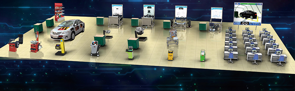
In the self-driving mode, the vehicle speed is about 5-30km/h, and the point-to-point automatic driving function is realized according to the planned route. Reasonable path planning, obstacles bypassing, and autonomous emergency braking can be realized during driving. Based on this equipment, it can carry out all-round practical training of intelligent connected vehicles from three aspects of perception, decision making and control.
1. Chassis wire-controlled verification. Through the experiment to master how the computing device is to achieve handshake communication with the car chassis, in-depth understanding of the role of the vehicle DBC file and the basic principles and processes of CAN.
Software system has vehicle control protocol code generation software, students understand the basic structure of the DBC file, then they can use the software tool to parse the DBC file, and quickly generate the vehicle control protocol code. The function of the code is to complete the chassis action control message filling and status reading & reporting.
2. Integrated control experiments of intelligent driving vehicle chassis, through the CAN protocol to control vehicle acceleration and deceleration, steering, driving mode switching.
Software equipped to the industrial computer, connected to the vehicle chassis through CAN BUS, then enter the software system and send commands to control the chassis, to check whether the chassis wire-controlled function is accurate. By sending different meanings of CAN protocol code, control the vehicle forward, backward, turn left, turn right, acceleration, braking, etc.
By looking at the signals coming back up from the chassis, whether they are the control values (steering, gear, speed, acceleration, etc.) that we send. You can see the value of each parameter and observe its change.
There are many other chassis data like this, including motor speed, motor controller status, etc. Programming can be extended for practical data analysis and control.
3.Intelligent driving GPS positioning experiments
The current intelligent driving positioning technology mainly relies on GPS, whose accuracy can reach the centimeter level, and our software uses GPS differential positioning in the positioning module. Equipped with GPS system setup software and document, GPS can be easily configured. The GPS experiment allows learning to understand the configuration process and working principle of GPS.
The experimenter connects the IMU inertial navigation to the GPS antenna correctly and sets the appropriate rod arm value, which is used to complete the GPS antenna to vehicle body coordinate system conversion.
4. Intelligent driving sensor calibration experiment
The sensors need to be calibrated to let each other know the relative position and increase the accuracy of control. It is mainly the external parameter calibration, including the calibration between LIDAR and IMU, calibration of camera, GPS. The hardware and software tools for calibration are provided, and calibration can be done quickly by following the established steps. Calibration is the basis for perception experiments.
5. Intelligent driving visual perception experiments.
Intelligent driving perception of external obstacles is mainly used for sensor and computing unit analysis of sensor data. Currently the most popular is LIDAR perception and camera vision perception. Among them, the principle of camera visual perception is to collect the image data and use the data for comparative analysis of machine learning models to get the type of obstacles and output.
This system software comes with machine learning models that can be used directly, and experimenters can also make their own learning models for algorithm verification innovation.
6.Intelligent driving ultrasonic detection experiments
Ultrasonic radar for close range detection, for parking and other close object warning. Experimenters can observe the recognition of close-range objects through our experimental process, including the distance of objects, etc.
7.Intelligent driving LIDAR detection experiments
LIDAR is used for obstacle recognition and assisted positioning in intelligent driving. After the point cloud data is collected, it is matched and analyzed according to the machine learning model brought by the software to derive the obstacle type, distance, moving direction, etc. Then the sensing module reports this information to the planning and decision-making layer to guide the vehicle to react accordingly.
Through the experimental process of LIDAR, it is possible to deeply understand how obstacles are detected by LIDAR, how the detection performance is, and how to use the detection results for system control.
8.Simple road map production experiment
Maps are a very important module for intelligent driving, and high precision maps are costly to produce. To facilitate learning, we developed a simple map generation program for experiments. Experimenters can also modify this generation procedure by themselves as needed to enrich the map content and achieve more meaningful map experiments.
9.Intelligent driving obstacle avoidance experiments
After the above experiments are done, the experimenter can conduct a comprehensive self-driving experiment, find an open field, let the vehicle move along the simple map, slow down when encountering people, or change lanes to avoid, and stop at the destination.
10.Continuously adjust the planning and control parameters based on the experimental results to make vehicle runs well, to achieve self-driving function.
11.This experiment can be used as a course design, which can encourage students to come up with novel ideas and achieve many research innovations.
12. Speed limit can be set as needed, and set the emergency stop button to ensure the safety during experiment.
13. It adopts electric energy.
14. Equipped with experiment software, guide students to fo hands-on experiments (including but not limited to programming), hardware and software open source, easy to research. c++ and Linux basic environment, moderate difficulty.
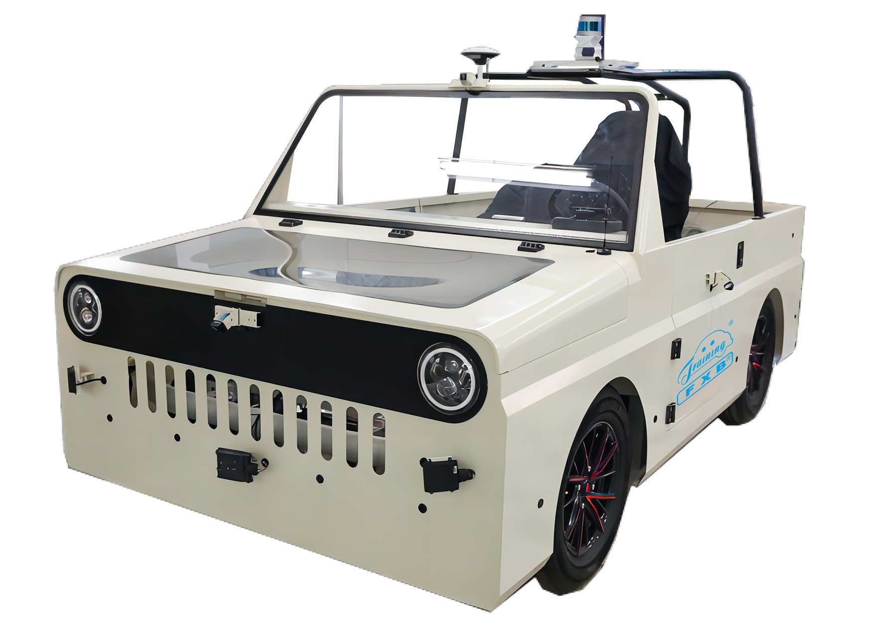
1. Basic parameters
Overall dimension (mm): not less than 3000 × 1400 × 1600 (length × width x height)
Maximum speed of 30km/h
Wheelbase not less than 2000mm
Minimum distance from the ground: 140mm
Pure electric range: not less than 100KM
2. Electrification system
Battery: battery voltage 72V, rated capacitance 100Ah
Driving motor: natural air-cooled, rated power not less than 3kw
Driving motor controller: input voltage 72V, maximum output power 15kW, maximum efficiency 98%, natural air-cooled, weight 1.5kg
Charger: rated input voltage 220V, maximum input current 16A, conversion efficiency 95%
3. Chassis system
Suspension: front and rear MacPherson type independent suspension
Steering system: EPS wire-controlled steering, control execution accuracy ± 2°
Braking system: front and rear disc brakes, wire-controlled braking, electronic parking, the response time of wire-controlled braking system is less than 200ms
Driving system: rear wheel drive, the response time of wire-controlled driving system is less than 200ms
4. Working conditions: charging ambient temperature range -10℃ to 50℃, driving ambient temperature range -20℃ to 50℃
5. Appearance parameters: the vehicle body adopts frame structure, and the vehicle front and rear hatches use transparent materials to facilitate teaching. The intelligent sensors, intelligent cockpit, wire-controlled steering, wire-controlled braking, computing platform can be repeatedly disassembled and assembled, and the installation position of millimeter wave radar is adjustable.
LIDAR:
1)Horizontal viewing angle: 360°
2)Vertical viewing angle 30° (-16°~+15°)
3)Range measurement: 0.3~80m (10% reflectivity)
4)Ranging accuracy: ±5cm (0.3~1m), ±2cm (1~80m)
5)16 lines of ranging channels
6)Providing 100 megabit Ethernet data output, including distance, rotation angle, reflectivity and other information
7)Working temperature: -20℃-65℃
8)Working voltage: 9-32V
9)Waterproof level: not less than IP67
Medium and long range millimeter wave radar:
1)Operating frequency: 77GHz
2)Modulation mode: FMCW
3)Transmission power: 10dBm
4)Ranging range: 1m~160m
5)Range accuracy: less than 0.3m
6)Speed range: 180km / h
7)Speed measurement accuracy: less than 0.5km / h
8)Maximum number of detection targets: not less than 30
9)Azimuth angle maximum coverage: 45 °
10)Pitch angle coverage: ±5 °
11)Detection cycle: 50ms
12)Power consumption: 7W
13)Weight: less than 300g
14)Waterproof level: IP67
Ultrasonic radar:
1)Distance detection: 0.1m - 3.5m
2)Detection distance accuracy: ±5cm
3)12-probe master control unit CAN data output
4)Working temperature meet: -40℃-85℃
5)Operating voltage: 9-16V
6)Waterproof level: IP67
Cameras:
1)Front view 120°, surround view 190°
2)Image resolution: not less than 1920*1080
3)Support frame rate: not less than 30fps
4)Camera data interface: GMSL2
5)Operating temperature: -40 ° C - 85 ° C
6)Waterproof level: not less than IP67
GPS combined navigation:
1)Combined GNSS and IMU navigation and positioning.
2)Position error accuracy not higher than 1.2cm when GNSS/BD signal is good, and course angle error accuracy not higher than 1°.
3)When GNSS signal is lost, the position deviation within 10m maintenance time is not less than 60s.
4)Data update frequency of 100Hz.
5)Support RS-232/485, network port, CAN/CANFD and other interfaces.
6)Including combined navigation host, 2 units of satellite antennas, connecting cables and positioning services, etc.
7)Working temperature: -30℃-70℃.
8)Working voltage: 9-32V.
9)Waterproof level: not less than IP67.
Computing platform:
1)With 2 units of high-performance processing chips (64-bit 8-core processor, main frequency not less than 2.2GHz, total computing power 60TOPS).
2)ROM storage not less than 32G.
3)With interfaces and modules: GMSL camera not less than 8 channels, Gigabit Ethernet port not less than 2 channels, CAN not less than 6 channels, LIN interface not less than 2 channels, RS232 not less than 4 channels.
4)Equipped with ASIL-D class microcontroller.
5)Working voltage: 9V to 16V.
6)Waterproof level: not less than IP67.
7)Operating temperature: -25℃ to 70℃.
1 unit of 16-line LIDAR, 1 unit of self-driving computing platform, 5 units of 77GHz millimeter wave radar, 1 unit of monocular camera, 4 units of 360 panoramic cameras, 1 set of GPS combined inertial navigation system, 1 unit of intelligent cockpit duplex screen, 12 units of ultrasonic radars, 1 unit of drive motor, 1 unit of wire-controlled motor controller, 1 unit of 72V power battery, 1 unit of body controller, 1 set of fuse box, 1 set of wire-controlled steering system, 1 set of wire-controlled brake system, 1 set of charger.