

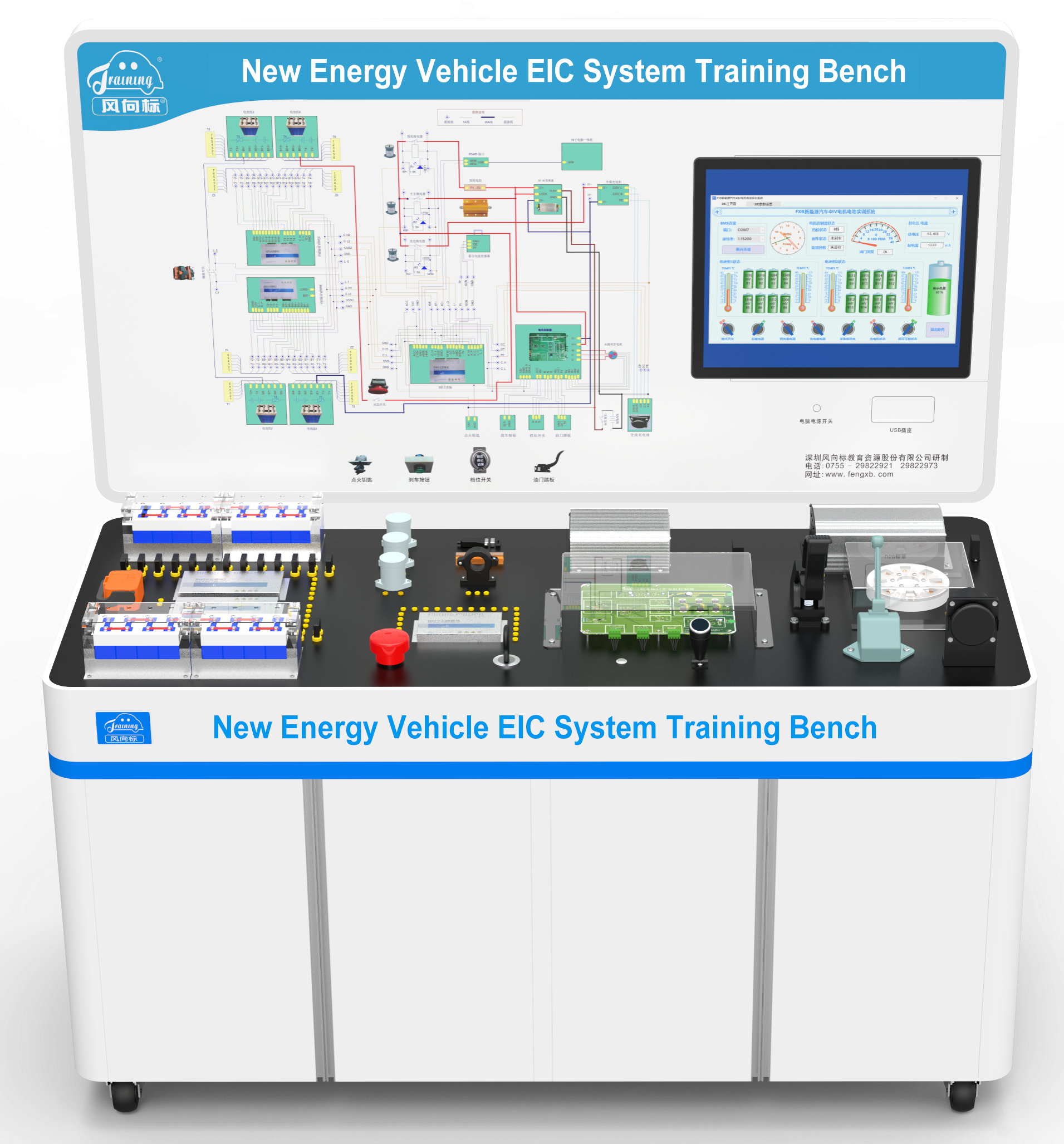
1. The device adopts a 51.2V power battery system for power supply, which is assembled in series by 16 3.2V/20AH lithium iron phosphate power batteries. The batteries are divided into two groups, and each group uses a battery acquisition board to collect the voltage of the single battery. That is, after the two BMS collect the battery voltage from the control board, the single battery voltage is transmitted to the BMS main control board through the CAN bus for analysis and management.
2. The BMS main control board can control the power supply of two slave control boards, and control the voltage acquisition module of the BMS slave control board to enter the low power consumption mode through CAN commands. The BMS main control board is connected to three external relays, namely the main control relay, the precharge relay and the charging relay. After the BMS main control board is powered on, it is necessary to check the voltage of each battery, the temperature of the battery pack, and the connection of 220V charging gun, current transformer and ACN. When all equipment is in normal state, relevant relays shall be connected as required to realize charging or discharging management. After receiving the data from the BMS slave control board, the BMS master control board combs and reassembles the packets, and reports them to the upper computer through the 485 interface according to the communication protocol.
3. If the charging gun is not connected or unplugged during power on, the BMS main control board will complete the battery pack and CAN communication detection. After confirming that they are all normal, first turn on the precharge relay to charge the large capacitance of the motor controller. When the voltage of the large capacitor approaches the total voltage of the battery pack, turn on the main relay to prevent ablation of the main relay contact, then disconnect the precharge relay, and notify the motor controller that the BMS power supply is normal through the CAN bus. During the discharge process, the BMS main control board will detect the discharge current, total battery voltage, single battery voltage and battery pack temperature in real time. When the voltage is too low or the current is too large, or the temperature of the battery pack is too high or too low, the electrical relay will be disconnected and opened in time, and the battery pack fault status will be reported to the motor controller through the CAN bus.
4. When the charging gun is connected, the BMS main control board will disconnect the electric relay, connect the charging relay to charge the battery pack, and real-time detect the charging current, total battery pack voltage, battery pack temperature and single battery voltage to ensure that each battery is in a good charging state. When the voltage difference between a single battery exceeds the user-set value, the BMS master control board will inform the BMS slave control board through the CAN bus to perform battery balancing, and the balancing current is about 100mA.
5. The motor controller will convert the DC into three-phase AC, monitor the signal of braking, the gear, and the throttle, and control the permanent magnet synchronous motor to work. The permanent magnet synchronous motor will increase the inertia disc, and realize energy recovery after releasing the throttle. Through experiments, students can fully master the parameter change law of the electric drive system during the inverter process. The BMS battery management system, motor controller, on-board charger, and DC-DC converter are all connected by lapped lines. It’s suitable for the learning of new energy power battery drive control principle.
II. Function Introduction:
1. The 51.2V power battery system is used for power supply, which is assembled in series by 16 3.2V/20AH lithium iron phosphate power batteries, with a total capacity of 51.2V/20AH. The battery shall be connected by special high-voltage power wires, with the negative pole marked in black and the positive pole marked in red to ensure the correct connection of the positive and negative poles.
2. The battery pack is divided into four groups, and each two groups corresponds to a BMS acquisition board. Each BMS acquisition board can collect the values of 8 single cells and two temperature sensors, and complete the voltage balance of the single cells in the group. The acquisition board uses a battery-specific voltage acquisition chip. Each acquisition board is controlled by an MCU. The MCU and the voltage acquisition chip are connected through an IIC interface with high and low voltage isolation. The acquisition chip is directly connected to the battery pack, isolated from the low-voltage 12V, and the MCU is powered by the low-voltage 12V battery. The IIC interface chip realizes high-voltage and low-voltage isolation and communication. The BMS slave control board mainly completes the functions of voltage acquisition, battery equalization, high voltage and low voltage isolation, and the BMS master control board completes the battery voltage calculation and management. The upper computer completes the functions of BMS status display and control parameter modification. The matching software includes the BMS main control board embedded program, the BMS slave control board embedded program. These two programs are written in C language, the development and debugging environment is MDK5.2, and the MCU is STM32F103C8T6, both of which provide source programs. The BMS battery management system is divided into three circuit boards, namely the BMS main control board, the BMS slave control board 1, and the BMS slave control board 2, all of which are double-sided circuit boards. And Isolation technology is adopted for high-voltage acquisition and low-voltage control circuit of BMS slave control board. The BMS main control board and the BMS slave control board use the CAN communication bus, and the 16 single batteries are connected with BMS master control board and BMS slave control board by splicing. The BMS management system provides matching circuit schematic diagram and PCB diagram, and the circuit control principle is clear.
3. The permanent magnet synchronous motor drive controller communicates with the BMS main control board through the CAN bus to obtain the working status of the BMS, report the status data of the motor controller to the BMS main control board, and upload it to the upper computer for display. The working states transmitted by the BMS to the motor controller mainly include the main relay, charging gun, battery pack undervoltage, overvoltage, overcurrent, and high or low temperature. The motor controller reports the brake, gear, throttle depth, motor speed and energy recovery status to the BMS master controller and upper computer. The motor controller converts high voltage direct current to alternating current and controls the direction and speed of motor rotation. The permanent magnet synchronous motor drive controller has the function of energy recovery. The power drive circuit is composed of 6 MOS tubes to form an IGBT drive circuit, with a clear circuit control principle. And the circuit design and schematic diagram, PCB diagram and control source program are provided. Equipped with electronic accelerator pedal to adjust motor speed. Equipped with brake signal control and D/N/R gear control. The controller has the function of energy recovery. The three-phase rectifier circuit is composed of six secondary tubes to rectify the three-phase AC recovered by the motor into DC. And the DC recovered voltage and current can be read on the display screen. There is a fault switch on the back of the motor controller, which can be toggled to set the internal circuit fault, and students analyze and detect controller line faults. The communication between the motor controller and the BMS main control module is connected by CAN communication, and the permanent magnet synchronous motor drive controller lap board has protection functions such as short circuit and reverse connection. The lap board of the permanent magnet synchronous motor drive controller adopts a double-sided circuit board, with the clear circuit control principle, equiped with matching circuit schematic diagram, and the connection with other components adopts the lap joint method.
4. Equiped with the matching national standard AC charging system. The BMS main control board determines whether the charging gun is inserted by detecting the CC signal provided by the charging gun, and feeds back the charging access signal to the charging gun through the CP to achieve the purpose of controlling the charging interface.
5. The DC-DC converter bonding plate converts 51.2V high voltage power into 13.8V low voltage power, which is used for power supply of the entire low-voltage circuit. The DC-DC converter bonding board has protection functions such as short circuit and reverse connection. The DC-DC converter lap board adopts double-sided circuit board, with clear circuit control principle, equipped with the circuit schematic diagram, and the connection with other components adopts the lap joint method.
6. The outer rotor hub permanent magnet synchronous motor is equipped with an inertia disk to increase the inertia during high-speed rotation. When the accelerator is released, the brake signal is pressed, and the feedback voltage and current are monitored in real time with the help of the clamp meter and the display screen.
7. The main material of the training bench is made of 40*40 aluminum alloy, which is artistic and solid. There are four casters at the bottom, which can move flexibly. And the casters have self-locking devices, which can fix the position.
8. The training bench is equipped with a automotive-specific clamp meter and a high-voltage test pen, which are used to measure the voltage, current and other parameters of the control line.
9. (Optional)The training bench is equipped with a teaching resource package software for the new energy buck-boost to describe the design and schematic diagram of the on-board charger, BMS battery management system, permanent magnet synchronous motor drive controller and DC-DC conversion circuit, and describe the structure and functions of main components in detail through three-dimensional animation mode. The main components can be clicked on and have basic parameters and performance descriptions. The teaching resource courseware is installed with a U disk, and can be played directly after being inserted into the computer, which is suitable for practical teaching.
10. Provide the upper computer software and source code, which can be run under the windows desktop system, and the software compilation environment is VS2012. With the help of a laptop, it can be connected to the BMS main control board through the USB to 485 interface, and read various battery and motor operating parameters and control state parameters of the BMS main control board, slave control acquisition and motor controller.
11. Equiped with BMS main control board, slave control board and motor controller embedded program source code, the development environment is MDK5.22. By analyzing the source program, it can further deepen the understanding of CAN communication, IIC communication, and 485 communication protocol, and deeply study the method of battery parameter acquisition, application of optical isolation technology, battery balancing algorithm, remaining power estimation algorithm.
12. Equipped with the embedded software of the new energy vehicle motor electronically controlled battery teaching system. Provides an open communication protocol, which defines the communication protocol between the host computer software and the BMS main control board, the BMS main control board and the BMS slave control board, and the BMS main control board and the motor controller. The protocol involves two communication methods, 485 and CAN bus, which is convenient for users to analyze the realization process of program source code according to the protocol, so as to achieve the purpose of combining theory and practice.
III. Product Parameters:
1. Dimensions of the platform (mm): not less than 1500*700*1560 (length*width*height)
2. Equipment working power: 220V AC, power not more than 500W
Equipment working temperature: -20°℃~+40°℃
3. Power battery
Power battery type: lithium iron phosphate power battery
Single battery: 3.2V20Ah
Number of batteries in series: 16
Total voltage: 51.2V
4. Motor controller
Type: permanent magnet synchronous motor drive controller (with energy recovery function)
Input voltage: 48V±10VDC
Rated power: 1KW
Peak power: 2KW
Speed control: electronic accelerator pedal signal
With brake signal control: with D/N/R gear control
5. Outer rotor hub permanent magnet synchronous motor
Size: not less than diameter 126.5* thickness 36mm
Weight: about 300g
Hollow shaft: Φ23mm
Stator: not less than diameter 115* thickness 10mm
Slot pole configuration: 27 slots and 30 poles
Working voltage: DC12V~48V
No-load speed: 2052rpm/48V
Rated voltage: 51.2V
Rated power: 400W
Rated current: 10A
Conversion efficiency: not less than 86%
IV. Basic Configuration:
16 Lithium iron phosphate power battery, 4 Temperature sensor, 4 Power battery plug-in special cable, 1 U-shaped patch cord, 25 50cm patch cord, 1 Smart car charger, 1 BMS battery management system main control board, 2 Slave control board, 1 Permanent magnet synchronous motor drive controller board, 1 DC-DC converter, 1 Outer rotor hub permanent magnet synchronous motor, 1 High voltage service switch, 1 Electronic accelerator pedal, 1 set of National standard charging system (charging gun and charging stand), 1 Precharge resistor, 3 High voltage control relay, 1 19-inch touch screen all-in-one, 1 digital automotive clamp meter, 1 high voltage test pen, 2 Flat head screwdriver, 2 Phillips head screwdriver, Movable aluminum alloy platform and teaching board.