

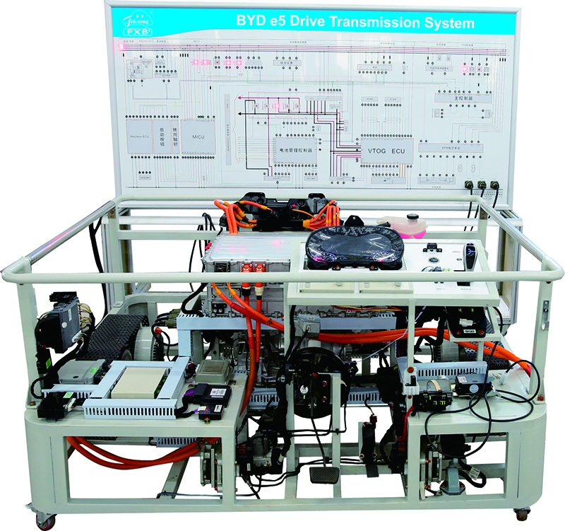
1.The main components are installed on the platform, including high-voltage electric control assembly, BMS power battery management controller, main controller assembly, MICU body controller, gateway control module, EPB electronic parking controller, and intelligent key controller. Both the high-voltage power line and the low-voltage control line are original vehicle parts, and the length is increased. The high-voltage power line is orange, with an additional protective bellows, and a warning sign is added at the joint. It is forbidden to plug and unplug any high-voltage power line under the condition of power on. CAN communication of the whole vehicle is integrated through the gateway. It enables students to understand the advanced nature of CAN communication network of new energy electric vehicle.
2.The training platform is connected with the training platform of power battery and management system. Input high-voltage direct current of power battery pack, invert to three-phase alternating current through high-voltage electric control assembly and output to drive motor.
3.With the help of supporting courseware data, the functions of main parts and pin definitions are fully described on the intelligent mobile platform display screen, including power battery management controller, VTOG ECU, MCU master controller, MICU body controller, Kless-ECU intelligent key system controller, accelerator pedal and other pin definitions.
4.The teaching board fully displays the working principle diagram of the high-voltage control system, and is equipped with detection terminals. With the help of a multimeter and oscilloscope, the parameter changes in various states can be detected in real time.
5.The training platform consists of a platform and a teaching board. The platform is placed horizontally and installed with main parts. Four casters, two universal wheels and two directional wheels are installed at the bottom of the platform, which can move flexibly. Meanwhile, universal casters are equipped with self-locking device, which can fix the position. Casters have low rolling resistance and wear resistance.
6.Transparent protective plates are added on both sides of the training platform to ensure the safety of high-voltage power line.
7.The left side of the training platform is equipped with the GB DC quick charging and AC charging ports. AC charging port supports AC 220VAC/7KW slow charging, but does not support 380V AC charging. Make sure the ground connection is reliable!
8.Emergency power off switch is equipped outside the training platform. In case of emergency, press the red button and the entire one-stop teaching system will be cut off to ensure the safety of the teaching process.
9.The training platform is installed in layers. The upper level is a high-voltage four-in-one control system, and the lower level is a drive motor and mechanical transmission system, which are installed at the same position as the real vehicle, making it convenient for students to master the connection and control relationship of the electric drive system.
10.Cooling fan and water tank are installed in front of the platform, in the same position as the real vehicle. Meanwhile, blowing hot air will not cause any harm to students.
11.Add a control panel on the left side of the frame. The accelerator and brake pedals are located directly below and operate in the same way as the real vehicle. Meanwhile, the OBD interface is moved to the control panel to facilitate data flow reading and fault detection.
12.The output end of the drive shaft is equipped with a load device to simulate the vehicle load system. By adjusting the load size at both ends, the variation rules of current and voltage and other parameters of the electric drive system under different working conditions (starting, acceleration, uniform speed, deceleration, half slope starting, etc.) can be truly reproduced.
13.It is equipped with intelligent fault setting and assessment system. Teachers set up the fault, and students analyze and find the fault points to grasp the real vehicle's fault handling ability. The fault setting shall be no less than 16 points, including three states of disconnection, accidental occurrence and short circuit to the ground.
14.The practical training platform is equipped with the practical training instruction, which fully describes the working principle of the practical training platform, training subjects, fault setting and elimination, and other key points.
1. Overall dimensions (mm) of the frame: Not greater than 1800*1450*1400 (length*width*height)
Dimensions (mm) of the teaching board: Not greater than 2400*1200*200 (length*height*thickness)
Dimensions (mm) of the teaching board base: Not greater than 2400*700*750 (length*width*height)
2. High-voltage power bus power supply: DC 604.8V
3. Low-voltage control operating power supply: DC 12V
4. High-voltage electric control assembly: (simple four-in-one controller, including motor controller module, 7KW vehicle charger and DC charging booster module, DC-DC converter module, and high-voltage distribution module)
Cooling mode: Water cooling
Control module: IGBT
Maximum output capacity: 180KW
Maximum output current: 270A
Level of protection: IP67
5. Permanent magnet synchronous motor: BYD
Rated power: 80KW
Maximum power: 160KW
Peak torque : 310N.m
Maximum speed: 12,000rpm
Cooling mode: Water cooling
Weight: 65Kg
6. Gearbox:
Total drive ratio: 9.342
Primary drive ratio: 3.158
Main reduction gear ratio: 2.958
1 high-voltage electric control assembly (four-in-one controller), 1 BMS power battery management controller, 1 main controller assembly, 1 MICU body controller, 1 gateway control module, 1 EPB electronic parking controller, 1 smart key controller, 1 AC charging port, 1 DC charging port, 1 gear position controller, combination meter, start button, 1 brake pedal assembly, 1 electronic accelerator pedal, 1 permanent magnet synchronous motor, 1 gearbox, 2 drive shafts, 2 brake discs, 2 flexible V-ribbed belts, 2 magnetic powder brakes, 2 manual tension controllers, 2 safety covers, 1 set of cooling system, 1 set of hydraulic brake system, 1 set of electric vacuum booster system, 1 12V 55AH maintenance-free battery, 1 AC charging port, 1 DC charging port, 1 set of orange high-voltage power line, 1 set of low-voltage control line, 1 mobile platform and teaching board.