


The control unit and peripheral sensor actuator and other devices of this system adopt the original vehicle (since the volume of new energy motor and battery air conditioner is too large, simulator parts are adopted). Each system is self-contained. On the panel, draw the pin diagram pin terminal of the control unit of the system, and draw the pin diagram pin terminal of each sensor and actuator. The system comes with a set of paper circuit connection schematic diagram. According to the schematic diagram of circuit connection, students can perform the experiment of circuit connection on the training box with the connecting wires equipped with 2mm banana plugs at both ends of the system.
1.Through the explanation and study of the circuit schematic diagram, students will know how to understand the circuit diagram, the different marking method of each terminal in different models, and the circuit symbol marking method of different devices.
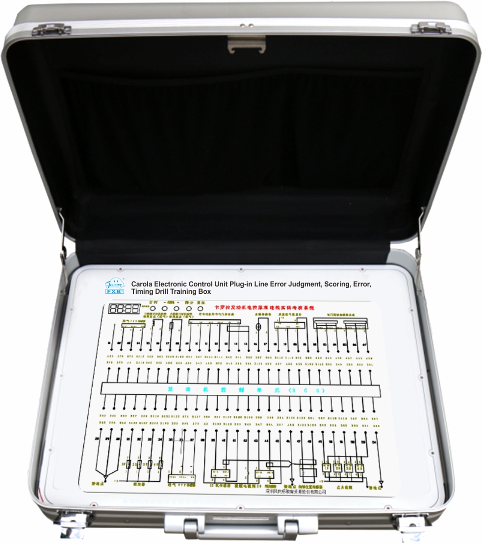
2.Through the observation of the physical objects on the panel, you can recognize different devices, correspond with the circuit symbols in the schematic diagram and take corresponding positions.
3.After learning the circuit diagram and understanding the device, the physical connection can be made according to the circuit schematic according to the terminal numbers of the control unit and peripheral devices provided on the panel;
4.After the connection is completed, each function button on the operation panel can be pressed to check the assessment result of the connection.
5.If the connection is correct, the system will automatically switch on the power supply to the control unit, so that the system is powered on, showing the phenomenon that the control unit should have. If a wire connection is not correct, the system refuses to supply power to the control unit system and prevent it from running on power. The purpose is to protect the control unit and peripheral devices from damage due to the wrong wire connection.
1. Operating voltage: AC 220V, DC 12V, DC 5V
2. Box dimensions: 540*450*220mm (length*width*height)
3.Weight: 5KG
1.A high-grade aluminum alloy one-time extrusion molding box body;
2.A control unit, and a set of sensor actuators associated with it;
3.A set of self-developed right and wrong judgment control board;
4.An operating power supply, and a power cord;
5.A panel with control unit and peripheral device pin terminal diagram;
6.One copy of the paper circuit schematic diagram;
7.One copy of practical training instruction;
8.40-65 wires for connecting each control unit and peripheral devices with a 2mm banana plug at both ends;
9.A display instrument with 4 digits on a panel;
10.6 function button switches: start, end, score, error message, up and down.