

2. Gear switch - used to simulate the P, R, N, D, D ±, D +, D-, S gear switches of the original vehicle.
3. D - Simulate the manual downshift switch of the original vehicle.
4. D+ - Simulate the manual upshift switch of the original vehicle.
5. Brake button - Simulate the brake pedal of the original vehicle.
6. Speed control knob - Simulate the accelerator pedal of the original vehicle.
7. 51 series SCM IC fastening socket - Used to place the SCM chip that has been written or needs to be programmed and downloaded.
8. ISP program download interface - For the SCM with this function (some manufacturers’ SCMs do not support this function), it is used to debug the download program.
9. Gear position - Display the position of the transmission P, R, N, D, S; where D and S directly display 1-6 gears, and D or S is not displayed.
10. Vehicle speed - Display the speed of the vehicle when it is in the R, D, S gear position, which is controlled by the "speed control knob".
11. LEDs - Indicate the power transmission route of each gear position, the K2 working state of the clutch K1, the position of the shift synchronizer, and the working condition of the parking pawl.
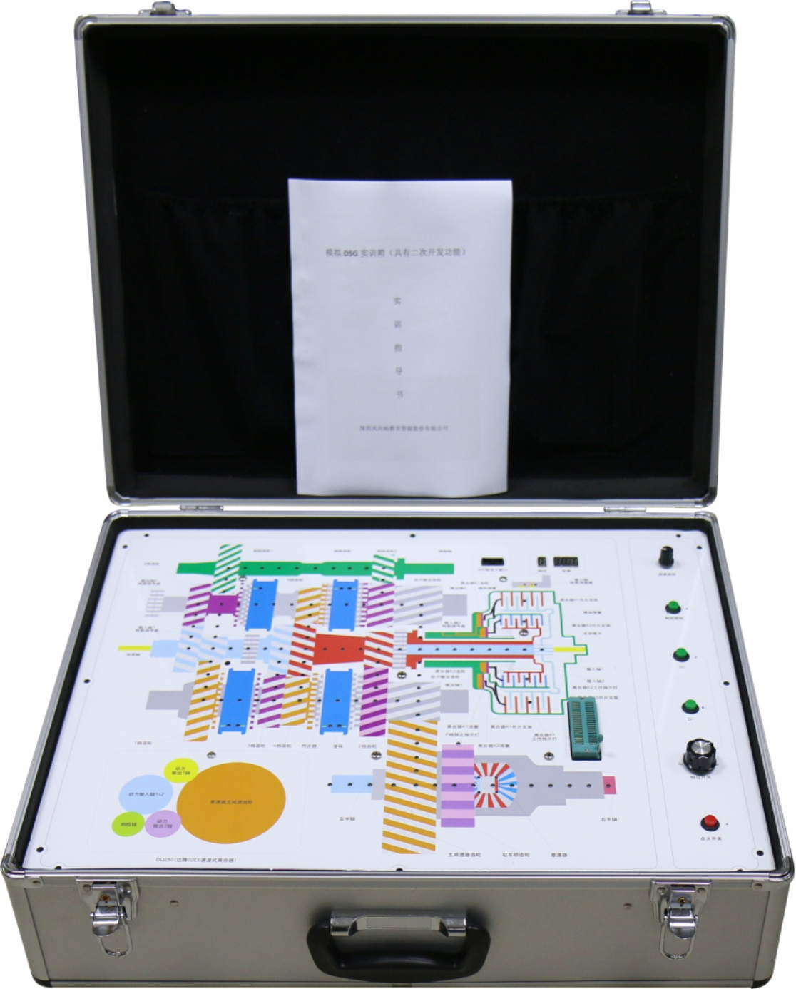
12. DSG dual-clutch mechanical structure plan - Understanding of the structure and familiarity with the names and functions of the various parts.
13. It can simulate the working process of Volkswagen 02E 6-speed wet dual-clutch automatic transmission.
14.Install a 4MM thick aluminum-plastic panel with a DSG mechanical structure plan in an aluminum alloy case.
15. Install the switch button knob digital meter in the configurations on the panel.
16. Install the DSG analog control unit on the back of the panel so that the LEDs are fixed in the corresponding holes.
17. The switching power supply is installed in the aluminum alloy case.
1. Power on - Pay attention to safety
Open the training box, take the power cord from the cover of the training box, connect one end of the power cord to the cabinet, and then plug the other end of the power cord into the 220V power socket. Press the “ignition switch” on the panel. At this time, the gear position shows the parking gear P, and the vehicle speed 000.
2. Rotate the “gear switch” clockwise by one gear. At this time, the gear position displays R, indicating that the reverse gear position has been reached. At this time, the speed display “000”. Adjust the “speed control knob” clockwise. The display value is increasing, as the reverse gear cannot be too fast. The system sets the maximum value to 63KM/H. During counterclockwise adjustment, the vehicle speed display value becomes smaller until 000 is displayed, this gear has no pre-engagement.
3. Continue to rotate the “gear switch” clockwise by one gear. At this time, the gear position displays n, indicating that it has reached the N gear position. At this time, the speed is displayed as “000”. no matter how to adjust the “speed control knob”. At this time, the speed display value is always 000, as there is no speed output in the neutral position. Observe the difference between the P and N gear positions, except for the P gear lock indicator light when the P gear is lit, the rest of the power transmission route is the same.
4. Continue to rotate the “gear switch” clockwise by one gear. At this time, the gear position displays one of the gear values from 1 to 6. Since the position of the speed adjustment knob is uncertain, the speed is displayed as 000~149KM/H, and the maximum speed is limited to 149. Adjust the “speed control knob”, the speed display value changes between 000~149, and the gear position changes between 1~6.
Define the shift points as follows: 20, 40, 60, 80, 100, which is artificially specified, and can be set arbitrarily when programming itself.
At this time, the pre-engaged gear - When the vehicle speed is in an accelerating trend, the upper gear is pre-engaged. When the vehicle speed is in a downward trend, the next gear is pre-engaged.
Press the “brake knob”, and the gear is pre-engaged to the next gear.
5. Continue to rotate the “gear switch” clockwise by one gear. At this time, the gear position is in the manual mode plus the downshift position, the original gear position and the vehicle speed are unchanged.
Press the “D+” button once, the gear position display increases one gear until the highest gear is gear 6. At this time, the pre-engaged gear is pre-engaged to the previous gear position.
Press the “D-” button once, the gear position display is lowered by one gear until the lowest gear is gear 1. At this time, the pre-engaged gear is pre-engaged to the next gear position.
At this time, no matter how to adjust the "speed knob", whether acceleration or deceleration, only the speed is changing, while the gear value and the pre-engaged gear remain the same.
Press the “brake knob”, and the pre-engagement is pre-engaged to the next gear.
6. Continue to rotate the “gear switch” clockwise by one gear. At this time, the gear position is in the S position, and the original gear position and speed change.
Adjust the "speed control knob", the highest gear is gear 2, the lowest gear is 1 gear, that is, it can only jump between gears 1 and 2, and the speed varies between 000-039.
Pre-engaged gears are only pre-engaged with each other between 1 and 2.
7. Rotate the “gear switch” counterclockwise. If it is not in a gear position, the phenomenon is the same as above, and thus there is no need to repeat, “Gear switch” can be arbitrarily pulled to any adjacent position.
8. Rotate the gear switch counterclockwise to the end, that is, the P position. Turn the “speed control knob” counterclockwise to the end, that is, the position where the vehicle speed is 0. Press the “ignition switch” to power off the system and unplug the power cord. Pull the power cord off the back of the training box, put it in the pocket of the box, close the training box, lock the buckle, and the experiment is completed.
9. Through the DSG mechanical structure plan drawn on the panel, you can understand the names and relative positions of the various parts that make up the DSG.
10. Through the various buttons and knobs on the control panel, you can truly feel the change of the value and the change of the flash LED of the power transmission route.
11. Pay attention to the pre-engaged position by accelerating, decelerating, and adding, reducing, and braking in manual mode.
12. For institutions with secondary development requirements, it is allowed to write their own programs. The ISP program download port or the chip that writes the program on the code writer is placed on the 40-pin DIP fastening seat to debug the program and demonstrate various different phenomena of the new program.
1. Size: 540 * 370 * 180 mm (length * width * height)
2. Weight: 6KG
3. Operating voltage: AC 220V, DC 12V, DC 5V