

1. When running the system, when the brake pedal is quickly pressed, if the vehicle speed exceeds 7KM/H, the ABS starts and participates in the brake (passive intervention). At this time, the brake pedal rebounds obviously.
2. If the vehicle speed is lower than 7KM/H, ABS will not participate in braking, and the brake at this time is a normal brake.
3. Set a single fault or composite fault for the speed sensors of the four wheels, or set a short circuit fault for the ABS pump, or set an open circuit fault for the positive and negative poles of the power supply, or set a short circuit fault for the short circuit, then the ABS fault indicator lights up. At this time, ABS does not work.
4. Automatically clear the fault code - clear the fault that has been set, restore the fault point to the normal state, the system is powered on again, the vehicle speed is lower than 20KM/H, the ABS fault indicator does not go out, when the speed exceeds 20KM/H, the ABS fails and the indicator light is off.
5. Use the car decoder to clear the fault - after setting the fault, the ABS fault indicator lights up. At this time, if the fault code is to be cleared, the system will be restored to normal, and the fault that has been set will be restored to the normal and usable state, which is not enough. At this time, the fault indicator is still lit. Only the option to clear the fault code entering the decoder is confirmed, the fault indicator is off, and the system returns to the normal state.
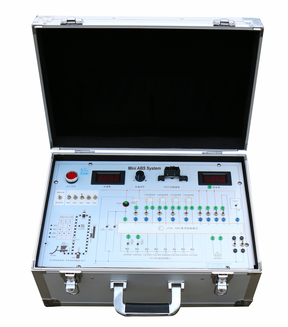
6. Through the OBD2 diagnostic socket, read the wheel speed value and compare it with the real situation. The two values are close to or even the same, indicating that the speed value displayed on the panel is true.
7. Through the frequency table set on the panel, it can be reflected that when the ABS is working, the frequency of the brake is 6~12 times/second, with an average of 9 times/second.
8. When the real speed/analog speed change switch is at the actual speed, the wheel speed sensor signal board is controlled by the permanent magnet synchronous DC gear motor. The generated vehicle speed signal is read by the wheel speed sensor and fed back to the ABS control unit. , is the real speed. when this switch is in the analog vehicle speed position, the motor that drives the signal disc is not controlled by the speed adjustment knob, the motor does not work, there is no rotation noise, but the vehicle speed signal is generated by the electronic module, and then sent ABS control unit for use by the ABS control unit.
9. When the system is working in ABS, it can hear the sound generated by the movement of the valve needle transmitted from the oil passage valve body. This sound is the frequency of the brake when braking. You can also hear the ABS pump running when ABS is working.
1. Size: 450*300*160mm (length * width * height )
2. Weight: 8.0KG
3. Operating voltage: AC 220V, DC 12V, DC 5V
ABS control unit assembly (including ABS pump and oil valve body),
4 ABS wheel speed sensor plugs,
4 speed sensors, 1 wheel speed sensor signal plate,
1 ABS fault indicator, 1 normal brake indicator,
1 DC 12V30W geared motor,
1 12V 29A switching power supply,
1 OBDII diagnostic socket,
1 digital display speedometer,
1 digital display frequency meter (can be switched, respectively detect the braking frequency of the four brake cylinders),
1 speed analog switch, 3 corresponding analog switches,
3 indicators for three stages of brake pumping (boost, pressure, decompression) during ABS operation,
1 pump and valve operation table during braking, and 1 electronic analog speed change switch for real speed switching.