

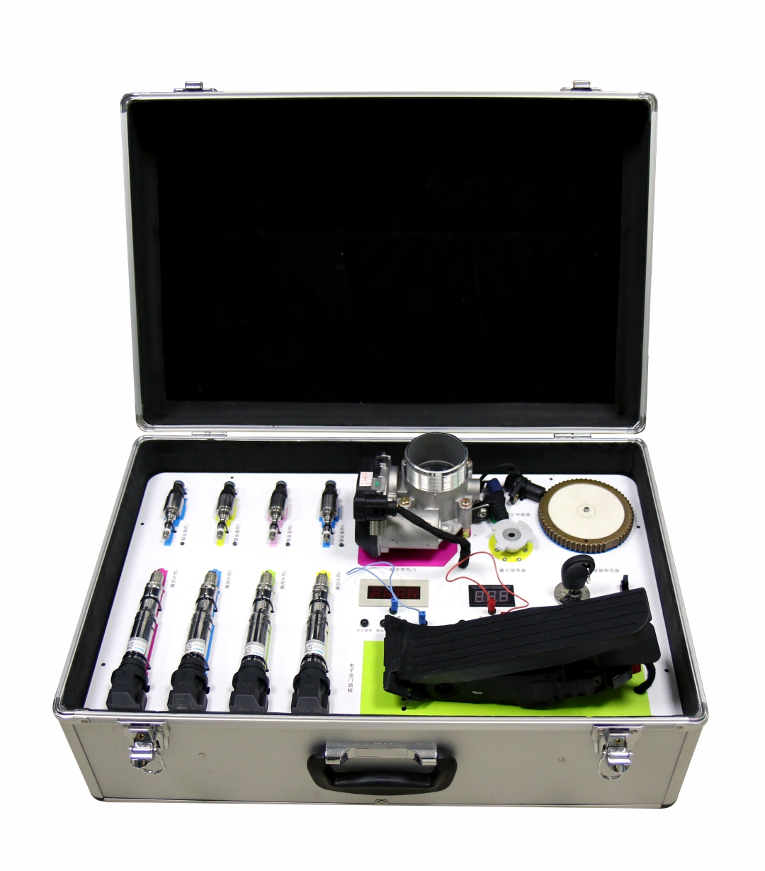
1. Using the sensor and actuator of the original vehicle’s engine part - crankshaft position sensor, crankshaft signal disc; camshaft position sensor, camshaft signal disc; electronic throttle pedal assembly, throttle assembly, independent ignition coil, fuel injector and other real parts related to the original vehicle.
2. Run the system to control the ignition and injection timing of the engine through the crankshaft signal and camshaft signal generated by the engine operation. In order to adapt to the teaching, it is necessary to visually see the ignition and injection sequence.
3. Run the system and change the number of engine pedals, ignition frequency, fuel injection frequency, and throttle opening by changing the accelerator pedal position.
4. For the convenience of teaching, the ignition injection frequency, crank signal frequency, camshaft signal frequency, throttle position sensor signal, accelerator pedal position sensor and other signals can be detected by the instrument.
5. Change the internal control program of the ECU so that the system can reflect the traditional multi-point port injection of fuel - spraying after the start of the suction stroke can also reflect the popular in-cylinder direct injection - the injection stroke is close to the top dead center of 60 degrees to 45 degrees. (Note: This system demonstrates the direct injection in the cylinder, the rest of the form shall be implemented by the student under the guidance of the teacher)
6. Under laboratory conditions, intuitively experience the various phenomena that occur when the engine is in the vehicle.
7. Learn to program some of the sensor signals and control some of the actuators.
8. Learn the design of the electronic circuit by understanding the internal circuit diagram of the engine control unit ECU (with a control schematic for reference).
1. Size: 560 * 380 * 220 mm (length * width * height )
2. Weight: 10.0KG
3. Operating voltage: AC 220V, DC 12V