


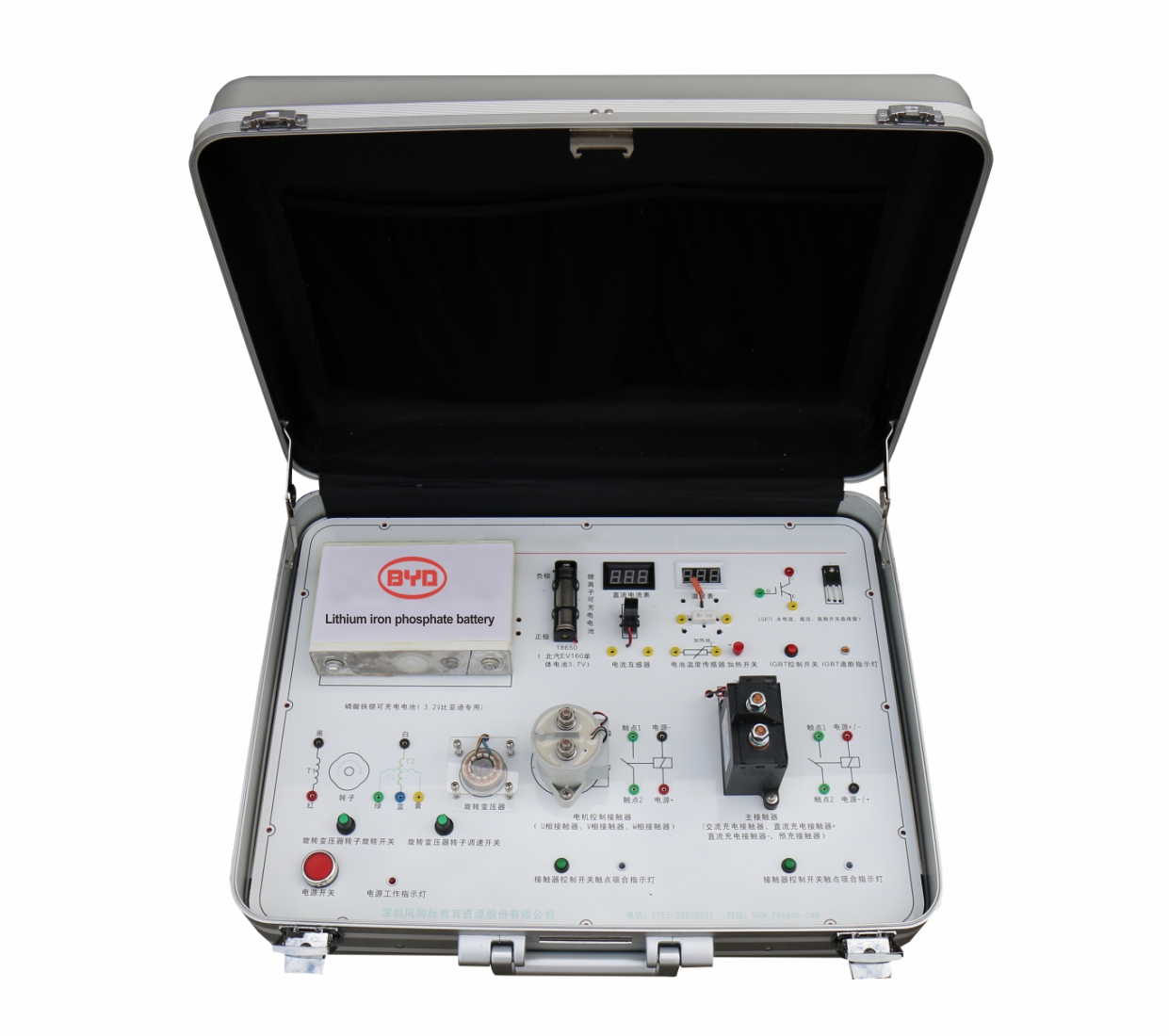
1. Know the structure and composition of each major component by observing the perception of the appearance of the main components of the electric vehicle.
2. By actually measuring the positive and negative electrodes of the battery, it can be known that the lithium iron phosphate battery single cell voltage is 3.2V, and the lithium ion single cell battery is 3.7V.
3. Through the actual operation and measurement, understand the role and use of the Hall current sensor.
4. The temperature sensor is heated by the temperature sensor heating system, and the data is collected through the internal battery temperature management system control board, and finally the temperature change value is reflected on the temperature meter.
5. By measuring the resistance of the temperature sensor during heating, it is found that the higher the temperature, the smaller the resistance of the sensor, that is, the temperature and the resistance are inversely proportional, that is, the negative temperature coefficient.
6. Through the test and measurement of IGBT amplification triode, it is found that IGBT triode has three characteristics of high current, high voltage and high frequency, which can fully meet the needs of DC-AC conversion of electric vehicles.
7. Through the actual measurement of the rotary transformer inside the motor, understand the working principle and advantages of measuring the number of revolutions of the motor.
8. Adjust the rotation speed of the rotary transformer rotor, and observe the change pattern of the input signal waveform and the two sets of output waveforms with an oscilloscope.
9. Actual connection operation and measurement of the main contactor (relay) detection terminal, observe the contact rule of the contact, and whether there is any relationship with the energization direction of the contactor coil.
10. Actual operation and measurement of the motor control contactor (relay), observe the contact rule of the contact, and whether there is any relationship with the energization direction of the contactor coil.
1.Size: 550*440*220mm (length * width * height)
2.Weight: 7KG
3.Operating Voltage: AC 220V, DC 12V,DC 5V;
1.Lithium iron phosphate battery and 18650 lithium ion single battery.
2. Two relays, Hall sensor and temperature sensor.
3. IGBT high frequency high voltage and high current drive triode.
4. Rotary transformer and 21 detection terminals.
5. DC current meter and thermometer.
6. Heating system and heating switch.
7. Rotary governor rotor speed control switch.
8. Power switch and one power working indicator.
9. 2 relay contact switches and 2 relay pull-in indicators.
10.220V to 12V 20A switching power supply.
11.System management control panel